Communication
8.6 RS485
S7-200 SMART
System Manual, 09/2015, A5E03822230-AC
403
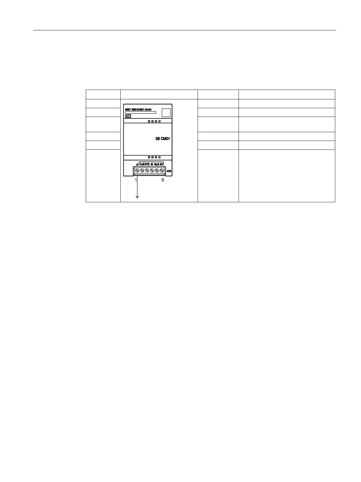
The CM01 signal board is RS485-compatible. The following table shows the connector that
provides the physical connection for the signal board and describes the pin assignments.
Table 8- 18 Pin assignments for the S7-200 SMART CM01 Signal Board (SB) port (Port 1)
CM01 Signal Board (SB) port (Port 1)
2 Tx/B RS232-Tx/RS485-B
3 Request-to-
RTS (TTL)
6 +5 V DC +5 V, 100 Ω series resistor
Biasing and terminating the network cable
Siemens provides two types of network connectors that you can use to easily connect
multiple devices to a network:
● Standard network connector
● Connector that includes a port which allows you to connect an HMI device to the network
without disturbing any existing network connections
The programming port connector passes all signals (including the power pins) from the
S7-200 SMART CPU through to the programming port, which is especially useful for
connecting devices that draw power from the S7-200 SMART CPU (such as a TD 400C).

 Loading...


