Communication
8.6 RS485
S7-200 SMART
404 System Manual, 09/2015, A5E03822230-AC
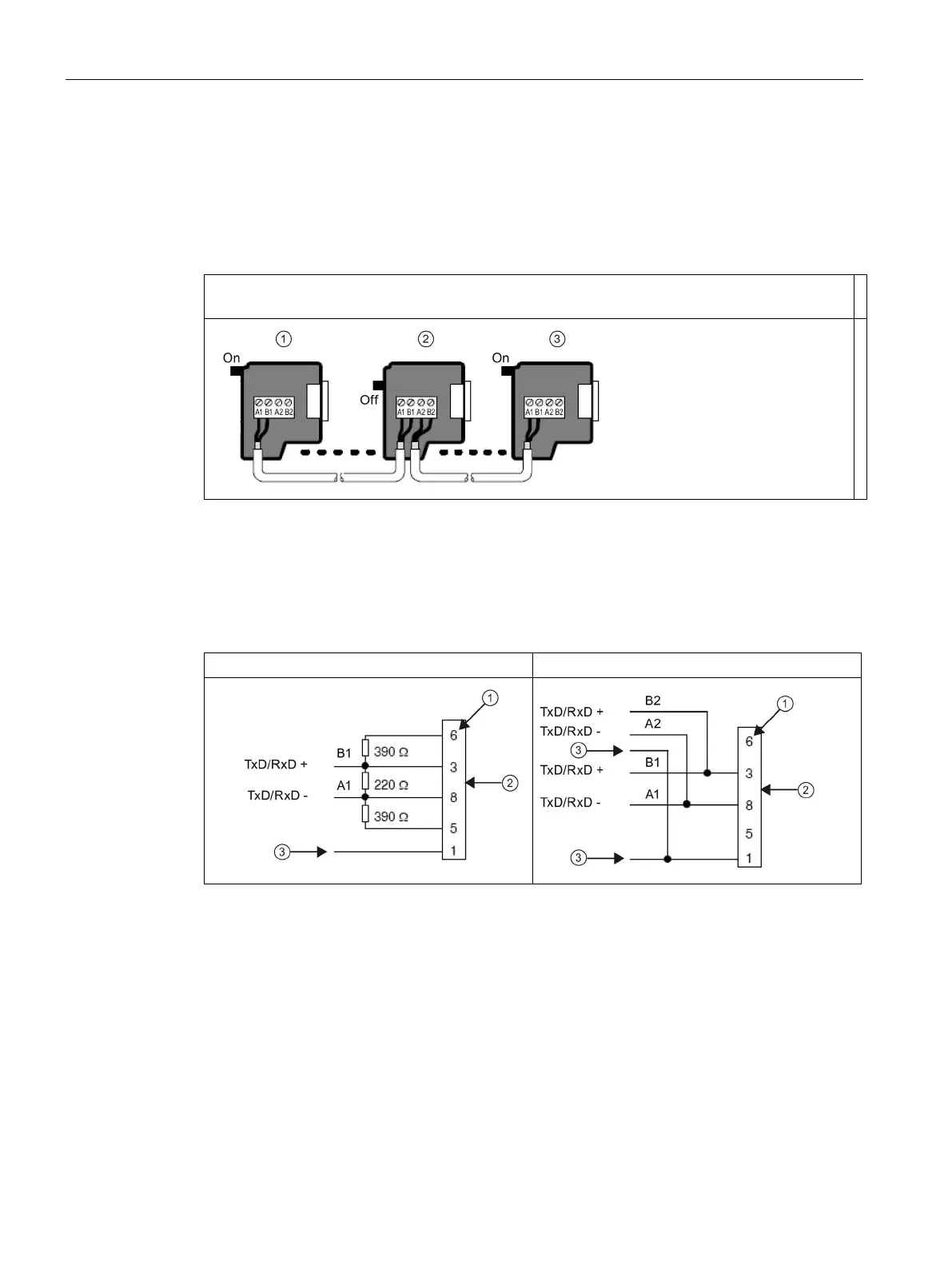
Both connectors have two sets of terminal screws to allow you to attach the incoming and
outgoing network cables. Both connectors also have switches to bias and terminate the
network selectively. The following shows typical biasing and termination for the cable
connectors.
Table 8- 19 Biasing and termination for cable connectors
Cable must be terminated and biased at both ends. Bare shielding: Approximately 12 mm (1/2 in)
must contact the metal guides of all locations.
Switch position = On: Terminated and biased
Switch position = Off: No termination or bias
③ Switch position = On: Terminated and biased
Table 8- 20 Termination and bias switch positions
Switch position = On: Termination and biased
Switch position = Off: No termination or bias
Pin number
Network connector

 Loading...


