PLC device configuration
6.1 Configuring the operation of the PLC system
S7-200 SMART
System Manual, 09/2015, A5E03822230-AC
133
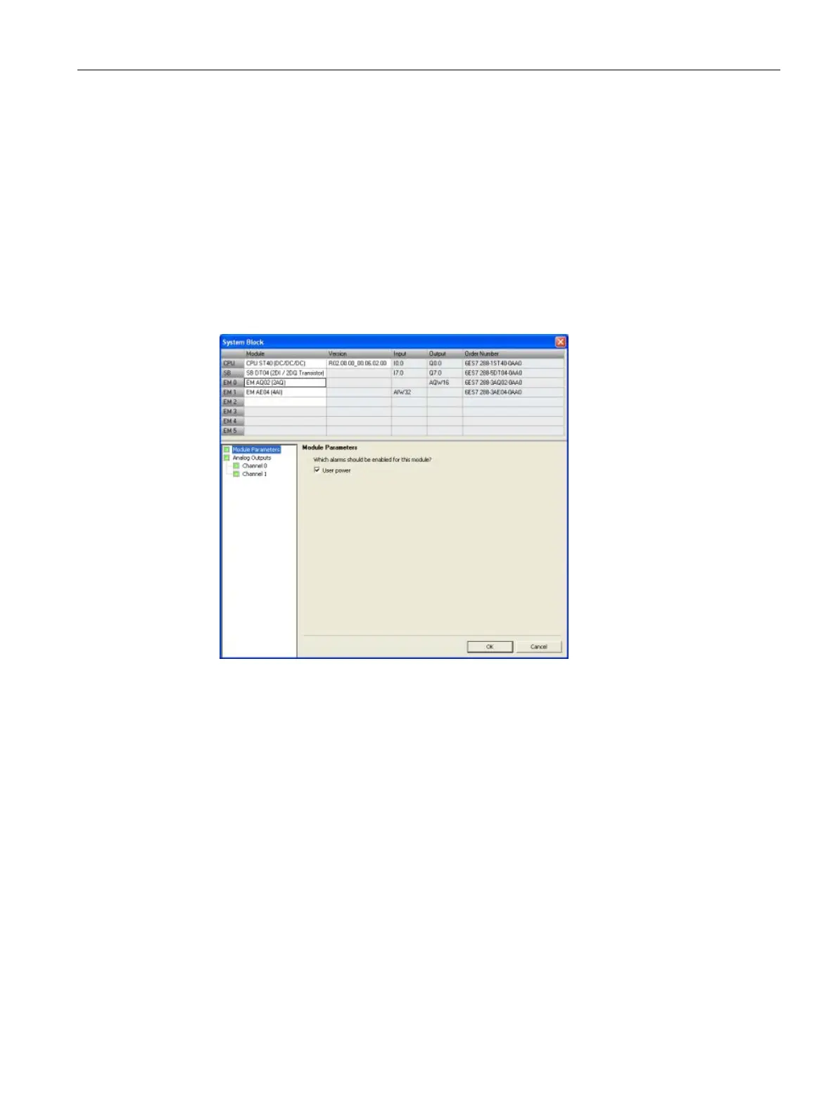
You select whether to enable or disable the following alarms for the selected channel of the
selected module:
● Upper limit exceeded (value > 32511)
● Lower limit exceeded (value < -32512)
● Wire break (for current channels only)
● Short circuit (for voltage channels only)
● User power (Configured in the system block "Module Parameters" node; see the figure
below.)
Reference to the analog outputs technical specifications
For further information on analog output range configuration, refer to the "Measurement
ranges of the analog outputs for voltage and current (SB and SM)" (Page 625) technical
specification.

 Loading...


