EasyManuals Logo

Siemens Simatic S7 Series System Manual

Siemens Simatic S7 Series
726 pages
To Next Page IconTo Next Page
To Previous Page IconTo Previous Page
Page #596 background imageLoading...
Page #596 background image
Technical specifications
A.2 S7-200 SMART CPUs
S7-200 SMART
596 System Manual, 09/2015, A5E03822230-AC
Technical data
CPU ST60 DC/DC/DC
CPU SR60 AC/DC/Relay
CPU CR60 AC/DC/Relay
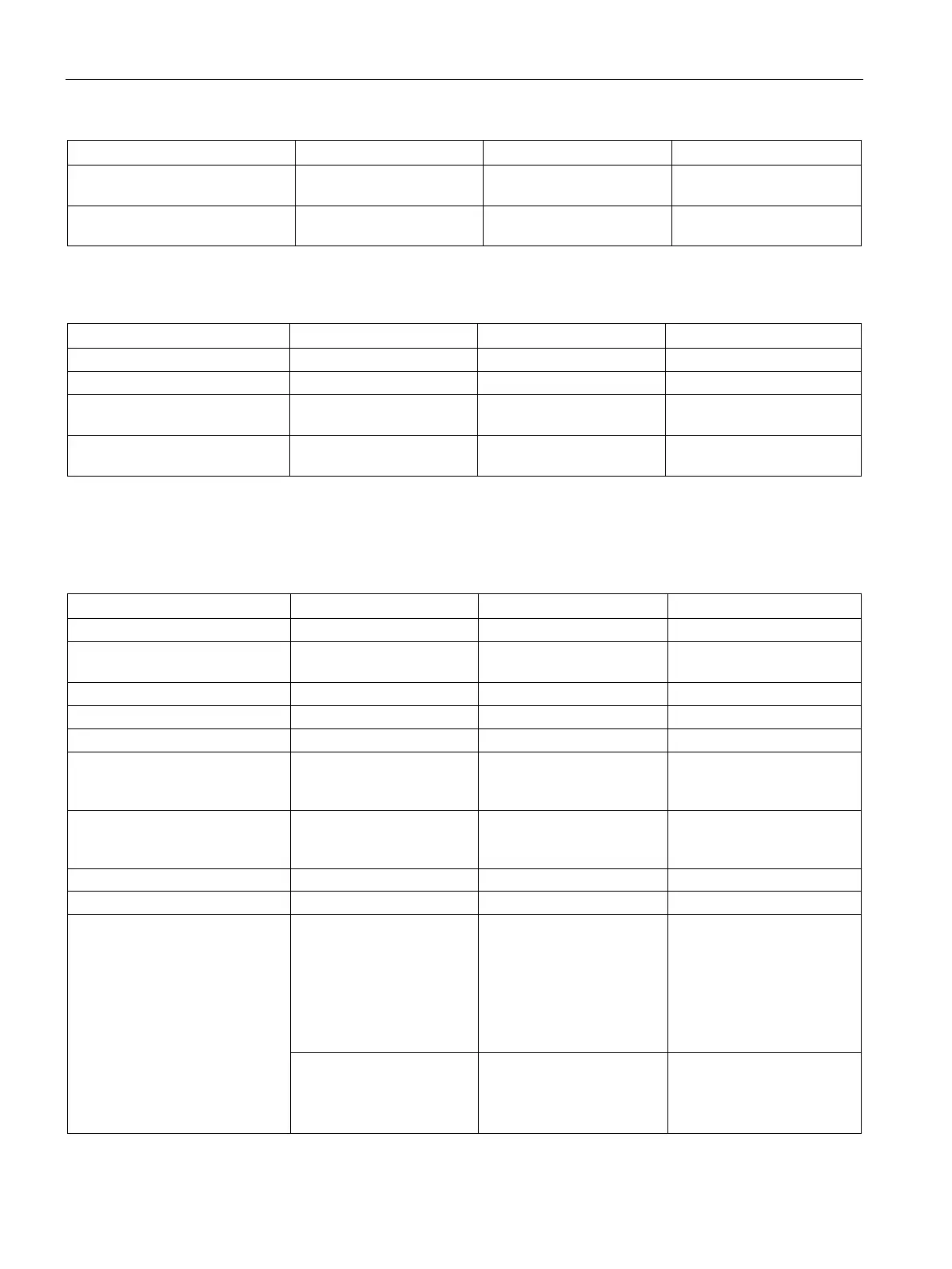
Hold up time (loss of power) 20 ms at 24 V DC 30 ms at 120 V AC
200 ms at 240 V AC
50 ms at 120 V AC
400 ms at 240 V AC
Internal fuse, not user replacea-
ble
3 A, 250 V, slow blow 3 A, 250 V, slow blow 3 A, 250 V, slow blow
Table A- 55 Sensor power
Technical data
CPU ST60 DC/DC/DC
CPU SR60 AC/DC/Relay
CPU CR 60 AC/DC/Relay
Voltage range
20.4 to 28.8 V DC
20.4 to 28.8 V DC
20.4 to 28.8 V DC
Output current rating (max.)
300 mA
300 mA
300 mA
Maximum ripple noise (<10
MHz)
< 1 V peak to peak < 1 V peak to peak < 1 V peak to peak
Isolation (CPU logic to sensor
power)
Not isolated Not isolated Not isolated
A.2.4.2
Digital inputs and outputs
Table A- 56 Digital inputs
Technical data
CPU ST60 DC/DC/DC
CPU SR60 AC/DC/Relay
CPU CR60 AC/DC/Relay
Number of inputs
36
36
36
Type Sink/Source (IEC Type 1
sink, except I0.0 to I0.3)
Sink/Source (IEC Type 1
sink)
Sink/Source (IEC Type 1
sink)
Rated voltage
24 V DC at 4 mA, nominal
Continuous permissible voltage
30 V DC, max.
30 V DC, max.
30 V DC, max.
Surge voltage
35 V DC for 0.5 sec.
Logic 1 signal (min.) I0.0 to I0.3: 4 V DC at 8 mA
Other inputs: 15 V DC at
2.5 mA
I0.0 to I0.3: 4 V DC at 8 mA
15 V DC at 2.5 mA
15 V DC at 2.5 mA
Logic 0 signal (max.) I0.0 to I0.3: 1 V DC at 1 mA
Other inputs: 5 V DC at 1
mA
5 V DC at 1 mA 5 V DC at 1 mA
Isolation (field side to logic)
500 V AC for 1 minute
Isolation groups 1 1 1
Filter times Individually selectable on
each channel (points I0.0 to
I1.5):
μs: 0.2, 0.4, 0.8, 1.6, 3.2,
6.4, 12.8
ms: 0.2, 0.4, 0.8, 1.6, 3.2,
6.4, 12.8
Individually selectable on
each channel (points I0.0 to
I1.5):
μs: 0.2, 0.4, 0.8, 1.6, 3.2,
6.4, 12.8
ms: 0.2, 0.4, 0.8, 1.6, 3.2,
6.4, 12.8
Individually selectable on
each channel (points I0.0 to
I1.5):
μs: 0.2, 0.4, 0.8, 1.6, 3.2,
6.4, 12.8
ms: 0.2, 0.4, 0.8, 1.6, 3.2,
6.4, 12.8
Individually selectable on
each channel (points I1.6
and greater):
ms: 0, 6.4, 12.8
Individually selectable on
each channel (points I1.6
and greater):
ms: 0, 6.4, 12.8
Individually selectable on
each channel (points I1.6
and greater):
ms: 0, 6.4, 12.8

Table of Contents

Other manuals for Siemens Simatic S7 Series

Questions and Answers:

Question and Answer IconNeed help?

Do you have a question about the Siemens Simatic S7 Series and is the answer not in the manual?

Siemens Simatic S7 Series Specifications

General IconGeneral
CPUVaries by model (e.g., S7-300, S7-400, S7-1200, S7-1500)
Communication InterfacesPROFIBUS, PROFINET, Ethernet, MPI
ProgrammingTIA Portal, STEP 7
Programming LanguagesLAD, FBD, STL, SCL, GRAPH
I/O ModulesDigital, Analog, Specialty modules available
Operating Temperature0°C to 60°C (standard models)
MountingDIN rail mounting
Operating Voltage24V DC or 120/230V AC (varies by model)
Protection ClassIP20 (standard models)
MemoryVaries depending on the S7 model. Includes work memory (RAM) for program execution, load memory (EEPROM or Flash) for program storage, and system memory for operating system functions. Memory sizes range from kilobytes to megabytes.

Related product manuals