Technical specifications
A.2 S7-200 SMART CPUs
S7-200 SMART
System Manual, 09/2015, A5E03822230-AC
597
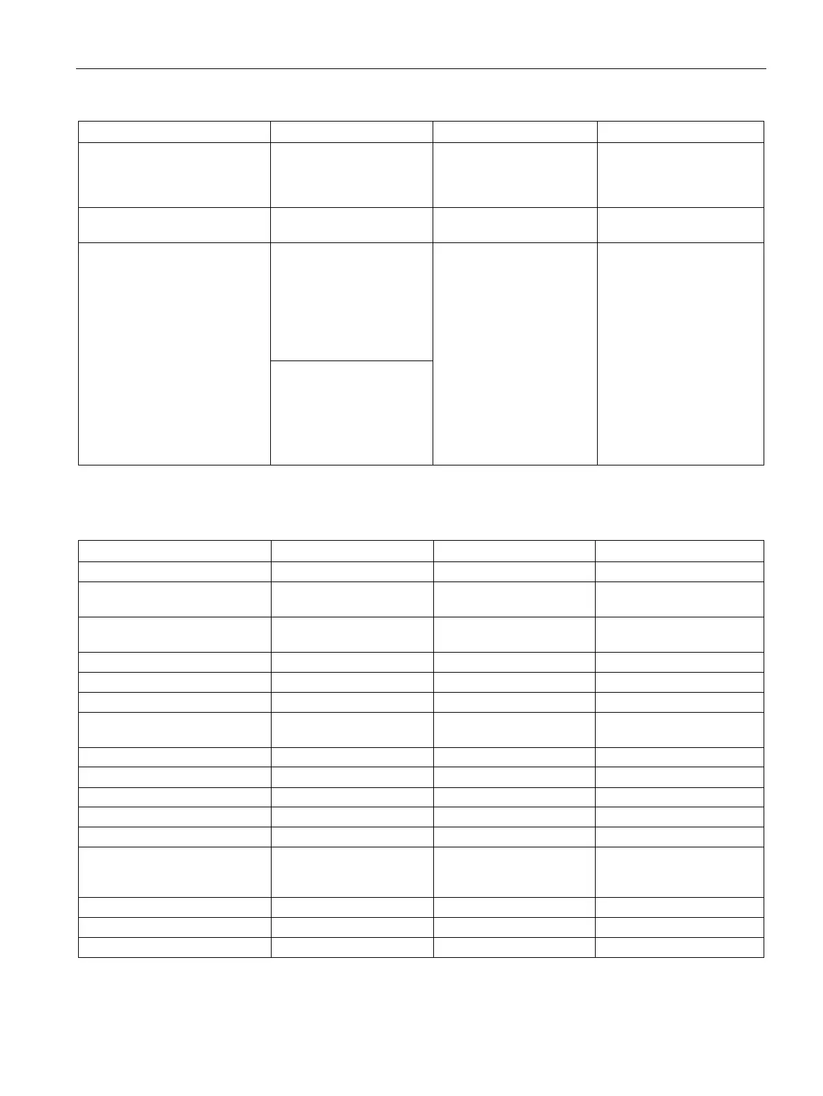
HSC clock input rates (max.)
(Logic 1 Level = 15 to 26 V DC)
4 HSC at 200 K Hz for
single phase
2 HSC at 100 K Hz for A/B
4 HSC at 200 K Hz for
single phase
2 HSC at 100 K Hz for A/B
4 HSC at 100 K Hz for sin-
gle phase
2 HSC at 50 K HZ for A/B
Number of inputs on simultane-
36 36 36
Cable length (max.), in meters I0.0 to I0.3:
Shielded (only):
• 500 m normal (low-
speed) inputs
• 50 m HSC (high-speed)
inputs
All inputs:
Shielded:
• 500 m normal inputs
• 50 m HSC inputs
Unshielded:
• 300 m normal inputs
All inputs:
Shielded:
• 500 m normal inputs
• 50 m HSC inputs
Unshielded:
• 300 m normal inputs
All other inputs:
Shielded:
• 500 m normal inputs
Unshielded:
• 300 m normal inputs
Table A- 57 Digital outputs
Type Solid state - MOSFET
Relay, dry contact Relay, dry contact
Voltage range 20.4 to 28.8 V DC 5 to 30 V DC or 5 to 250 V
5 to 30 V DC or 5 to 250 V
Logic 1 signal at max. current
Logic 0 signal with 10 KΩ load
Rated current per point (max.)
Rated current per common
6 A 10 A 10 A
ON state resistance 0.6 Ω max. 0.2 Ω max. when new 0.2 Ω max. when new
Leakage current per point
Isolation (field side to logic) 500 V AC for 1 minute 1500 V AC for 1 minute
(coil to contact) None (coil
1500 V AC for 1 minute (coil
to contact) None (coil to
Isolation between open contacts

 Loading...


