Debugging and troubleshooting
10.7 Hardware troubleshooting guide
S7-200 SMART
System Manual, 09/2015, A5E03822230-AC
465
Overview of debugging and monitoring features (Page 453)
How to display status in the editor windows (Page 456)
How to display status in a status chart (Page 460)
How to download a program (Page 75)
Timestamp mismatch error (Page 663) (ensuring that project in programming device
matches project in PLC)
Cross reference and element usage (Page 454) (ensuring that program edits do not cause
duplicate assignments)
Forcing values (Page 462)
Forcing outputs in STOP mode (Page 463)
Hardware troubleshooting guide
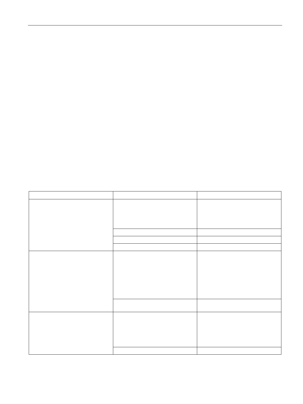
Table 10- 1 Troubleshooting guide for the S7-200 SMART hardware
Outputs stop working The device being controlled has
caused an electrical surge that dam-
aged the output
When connecting to an inductive load
(such as a motor or relay), a proper
suppression circuit should be used.
Refer to
the wiring guidelines in Chap-
Wiring loose or incorrect
Check load against contact ratings
Check the CPU for forced I/O
ERROR light on the CPU turns on
(Red)
Electrical noise Refer to
the wiring guidelines in Chap-
ter 3. It is very important that the con-
trol panel is connected to a good
ground and that high voltage wiring is
not run in parallel with low voltage
wiring.
Connect the M terminal on the 24 V DC
Sensor Power Supply to ground
Component damage Send in hardware for repair or re-
None of the CPU LEDs turn on Blown fuse Use a line analyzer and monitor the
input power to check the magnitude
and duration of the over-voltage spikes.
Based on this information, add the
proper type surge arrestor device to
your power wiring.
Reversed 24 V power wires
Refer to the wiring guidelines in Chap-

 Loading...


