Debugging and troubleshooting
10.7 Hardware troubleshooting guide
S7-200 SMART
466 System Manual, 09/2015, A5E03822230-AC
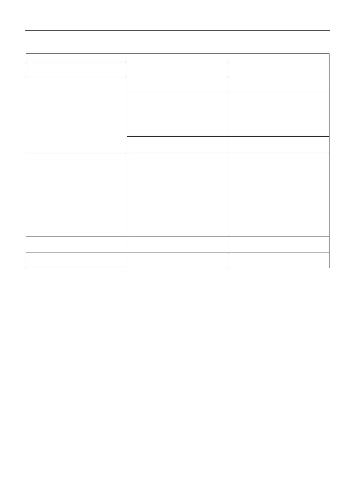
Incorrect voltage
ter 3 for information about installing the
field wiring.
Intermittent operation associated with
high energy devices
Improper grounding Refer to
the wiring guidelines in Chap-
ter 3.
Routing of wiring within the control
cabinet
It is very important that the control
panel is connected to a good ground
and that high voltage wiring is not run
in parallel with low voltage wiring.
Connect the M terminal on the 24 V DC
Sensor Power Supply to ground.
Time delay on input filters too short Increase the input filter delay in the
Serial communications (RS-485 or RS-
232) are damaged when connecting to
an external device.
Either the port on the external device or
the port on the CPU is damaged.
The communications cable can provide
a path for unwanted currents if all non-
isolated devices, such as PLCs, com-
puters, or other devices do not share
the same network circuit common ref-
erence. The unwanted currents can
cause communications errors or dam-
age to electric circuits.
• Refer to the wiring guidelines in
Chapter 3 and to the network guide-
lines in Chapter 8.
• Purchase network isolators or iso-
lated RS485-to-RS485 repeaters
when you connect devices that do
not have a common electrical refer-
ence.
Refer to Appendix F for information
about article numbers for S7-
Other communications problems
Refer to Chapter 8 for information
about network communications.
Error handling Refer to Appendix C for information

 Loading...


