PID loops and tuning
11.6 Notes concerning PV out-of-range (result code 3)
S7-200 SMART
476 System Manual, 09/2015, A5E03822230-AC
Notes concerning PV out-of-range (result code 3)
The process variable is considered to be in-range by the auto-tuner if its value is greater
than 0.0 and less than 1.0.
If the PV is detected to be out-of-range during the auto-hysteresis sequence, then the tuning
is immediately aborted with a process out-of-range error result.
If the PV is detected to be out-of-range between the starting point of the tuning sequence
and the fourth zero-crossing, then the output step value is cut in half and the tuning
sequence is restarted from the beginning. If a second PV out-of-range event is detected after
the first zero-crossing following the restart, then the tuning is aborted with a process out-of-
range error result.
Any PV out-of-range event occurring after the fourth zero-crossing results in an immediate
abort of the tuning and a generation of a process out-of-range error result.
STEP 7-Micro/WIN SMART includes a PID Tune control panel that allows you to graphically
monitor the behavior of your PID loops. In addition, the control panel allows you to initiate the
auto-tune sequence, abort the sequence, and apply the suggested tuning values or your own
tuning values.
To use the control panel, you must be communicating with the CPU and a wizard-generated
configuration for a PID loop must exist in the CPU. The CPU must be in RUN mode for the
control panel to display the operation of a PID loop.
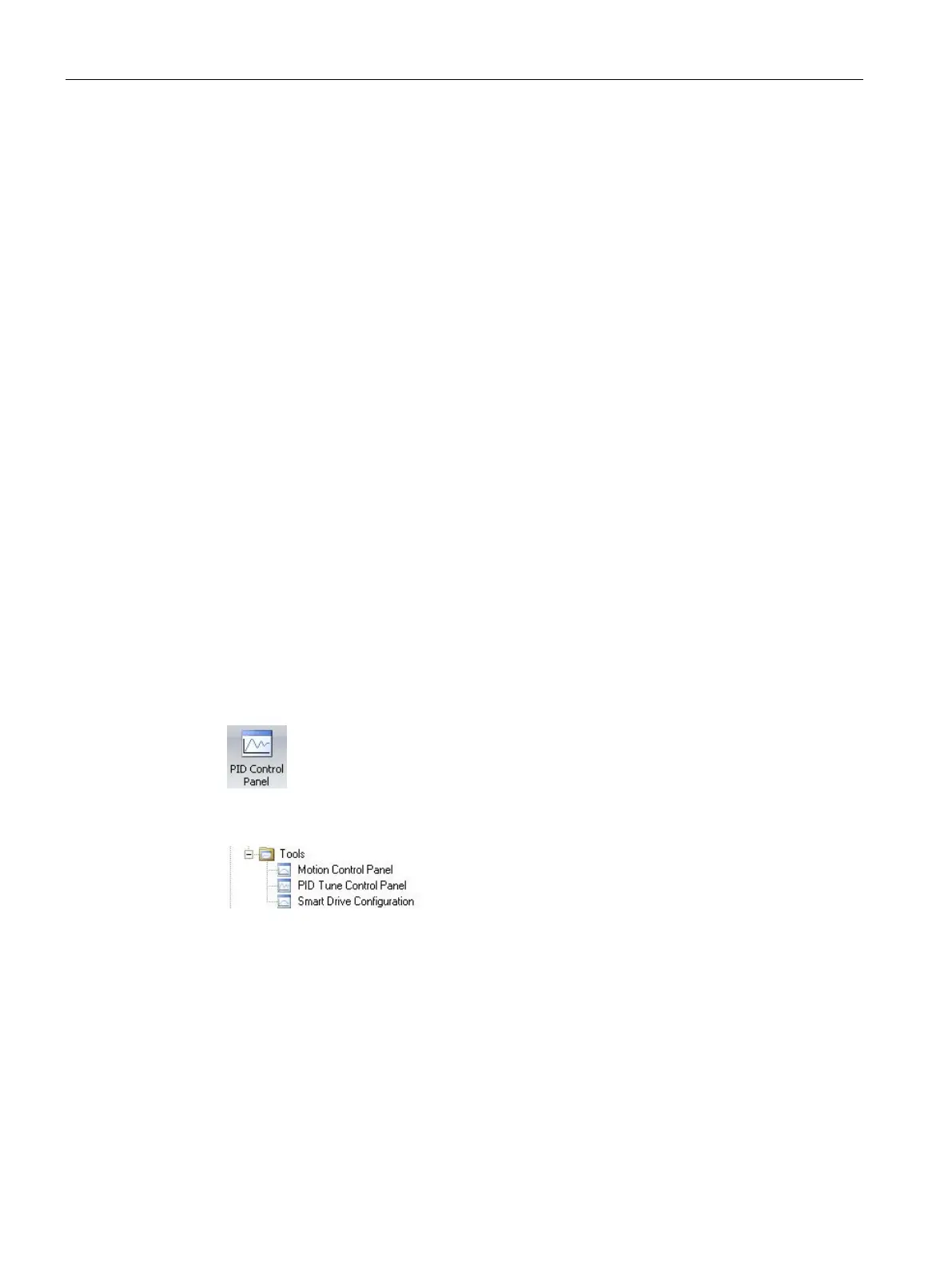
To open the PID control panel, use one of the following methods:
● Click the "PID Control Panel" button from the Tools area of the Tools menu ribbon strip.
● Open the Tools folder in the project tree, select the "PID Tune Control Panel" node and
press Enter; or double-click the "PID Tune Control Panel" node.

 Loading...


