Technical specifications
A.5 Thermocouple and RTD expansion modules (EMs)
S7-200 SMART
636 System Manual, 09/2015, A5E03822230-AC
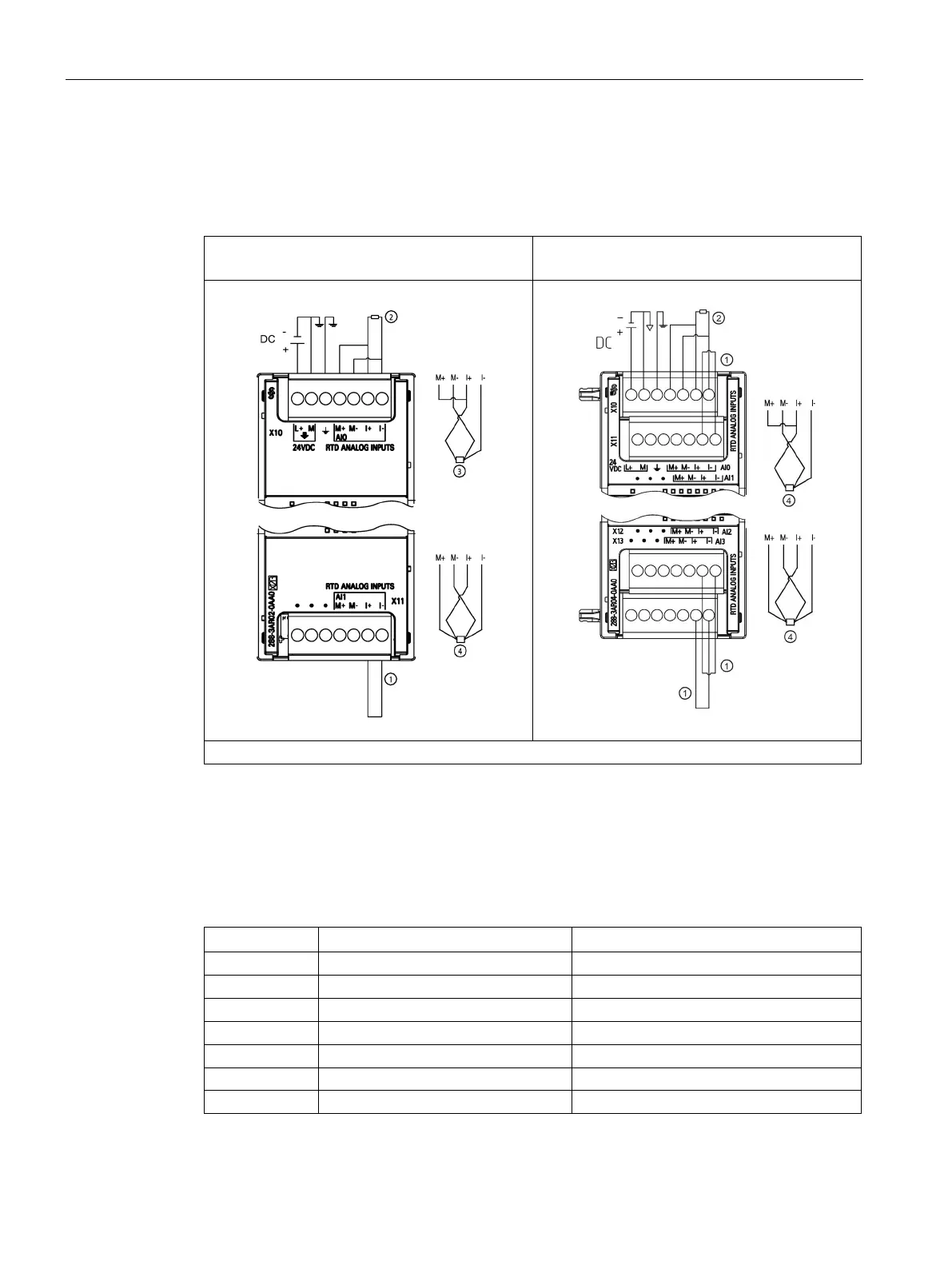
Table A- 122 Wiring diagrams for the EM AR02 RTD 2 x 16 bit (6ES7 288-3AR02-0AA0) and EM
AR04 RTD 4 x 16 bit (6ES7 288-3AR04-0AA0)
EM AR02 RTD 2 x 16 bit
(6ES7 288-3AR02-0AA0)
EM AR04 RTD 4 x 16 bit
(6ES7 288-3AR04-0AA0)
Note: Connectors must be gold. See Appendix F, Spare parts and other hardware, for article number.
Loop-back unused RTD inputs
② 2-wire RTD ③ 3-wire RTD ④ 4-wire RTD
Note: Connectors must be gold. See Appendix F, Spare parts and other hardware for article number.
Table A- 123 Connector pin locations for EM AR02 RTD 2 x 16 bit (6ES7 288-3AR02-0AA0)
6 AI 0 I+/RTD AI 1 I+/RTD

 Loading...


