PLC device configuration
6.1 Configuring the operation of the PLC system
S7-200 SMART
System Manual, 09/2015, A5E03822230-AC
123
Data retention after CPU power interruption
The CPU performs the following actions regarding retentive memory at power down and
power up:
●
The CPU saves the memory ranges designated as retentive to permanent memory.
●
The CPU first clears V, M, C, and T memory, copies any initial values from the data block
to V memory, and then copies the saved retentive values from permanent memory to
RAM.
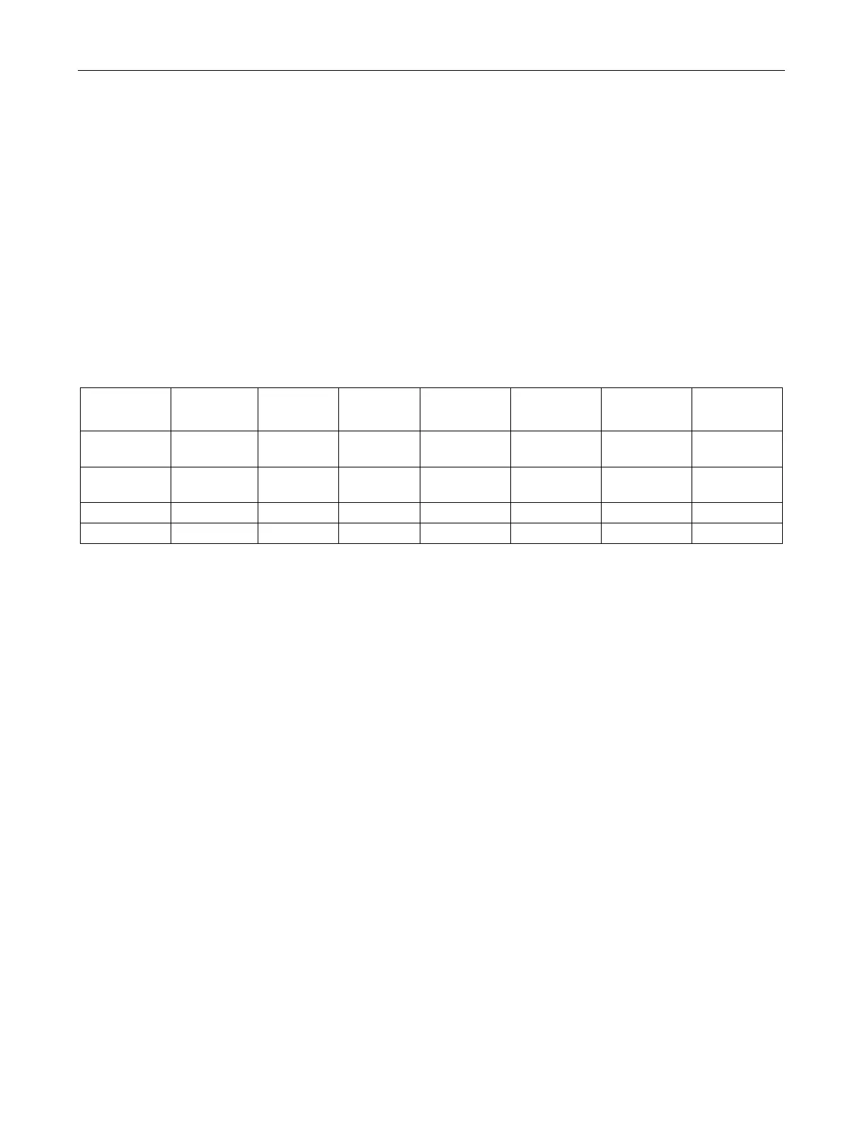
S7-200 SMART CPU memory addresses for retentive ranges
V Data Memory VB0-
VB0-
VB0-VB8191 VB0-VB12281 VB0-VB16383 VB0-VB20479
T Timers T0-T31,
T64-T95
T0-T31,
T64-T95
T0-T31,
T64-T95
T0-T31,
T64-T95
T0-T31,
T64-T95
T0-T31,
T64-T95

 Loading...


