Program instructions
7.1 Bit logic
S7-200 SMART
System Manual, 09/2015, A5E03822230-AC
153
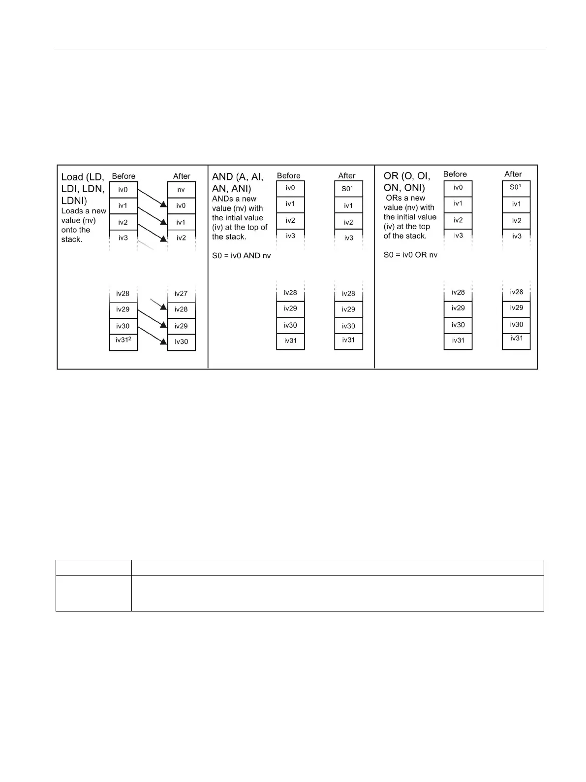
Input networks and the logic stack
As shown in the following figure, the CPU uses a logic stack to combine the logic states of
STL inputs. In these examples, "iv0" to "iv31" identify the initial values of the logic stack
levels, "nv" identifies a new value provided by the instruction, and "S0" identifies the
calculated value that is stored in the logic stack.
1
S0 identifies the calculated value that is stored in the logic stack.
2
After the execution of a Load, the value iv31 is lost.
Output networks and the logic stack
ENO is a binary output for boxes in LAD and FBD. If a LAD box has power flow at the EN
input and is executed without error, the ENO output passes power flow to the next LAD
element. You can use the ENO as an enable bit that indicates the successful completion of
an instruction. The ENO bit is used with the top of stack to affect power flow for execution of
subsequent instructions. STL instructions do not have an EN input. The top of the stack must
have a value of logic 1 for conditional instructions to be executed. In STL there is no ENO
output. However, the STL instructions that correspond to LAD and FBD instructions with
ENO outputs set a special ENO bit. This bit is accessible with the AND ENO (AENO)
instruction.
AENO is used in the STL representation of LAD/FBD box ENO bit. AENO performs a logical AND of
the ENO bit with the top of stack for the same effect as the ENO bit of a LAD/FBD box. The result of the
AND operation is the new top of stack value.

 Loading...


