Program instructions
7.6 Counters
S7-200 SMART
System Manual, 09/2015, A5E03822230-AC
225
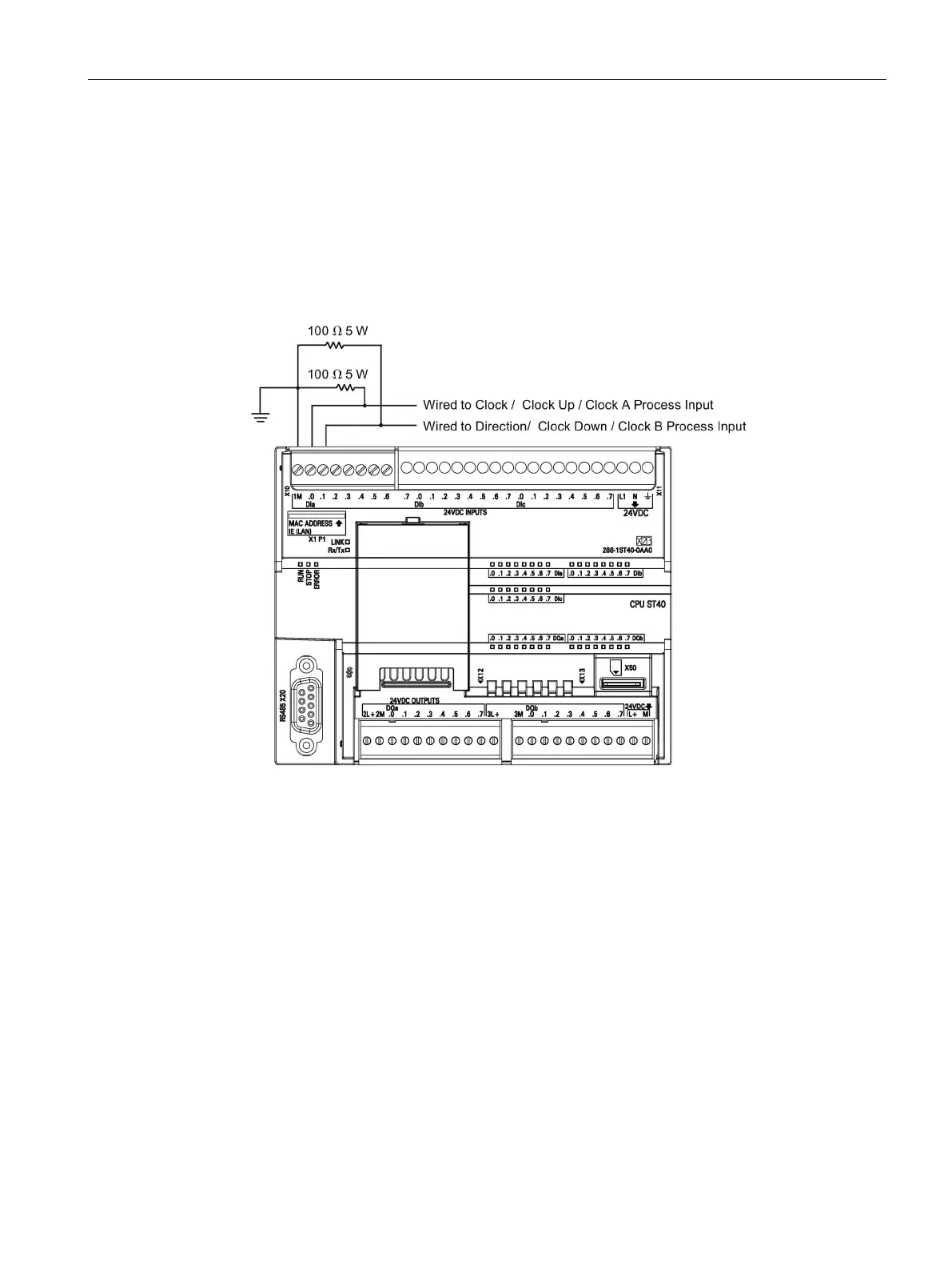
● If the device generating the HSC input signals does not drive the input signals both high
and low, then signal distortion can occur at high speeds. This can occur if the output of
the device is an open-collector transistor. When the transistor turns off, there is nothing
driving the signal to a low state. The signal will transition to a low state, but the time to do
so will be dependent on the input resistance and capacitance of the circuitry. This
condition can result in missed pulses. This condition can be prevented by wiring a pull-
down resistor to the input signals as seen in the following figure. Since the input voltage
of the CPU is 24V, the resistor would have to be rated for a high wattage. A 100 ohm 5
Watt resistor is a suitable choice.
Figure 7-1 Pull-down resistor wiring for open-collector HSC input drivers

 Loading...


