Program instructions
7.6 Counters
S7-200 SMART
System Manual, 09/2015, A5E03822230-AC
227
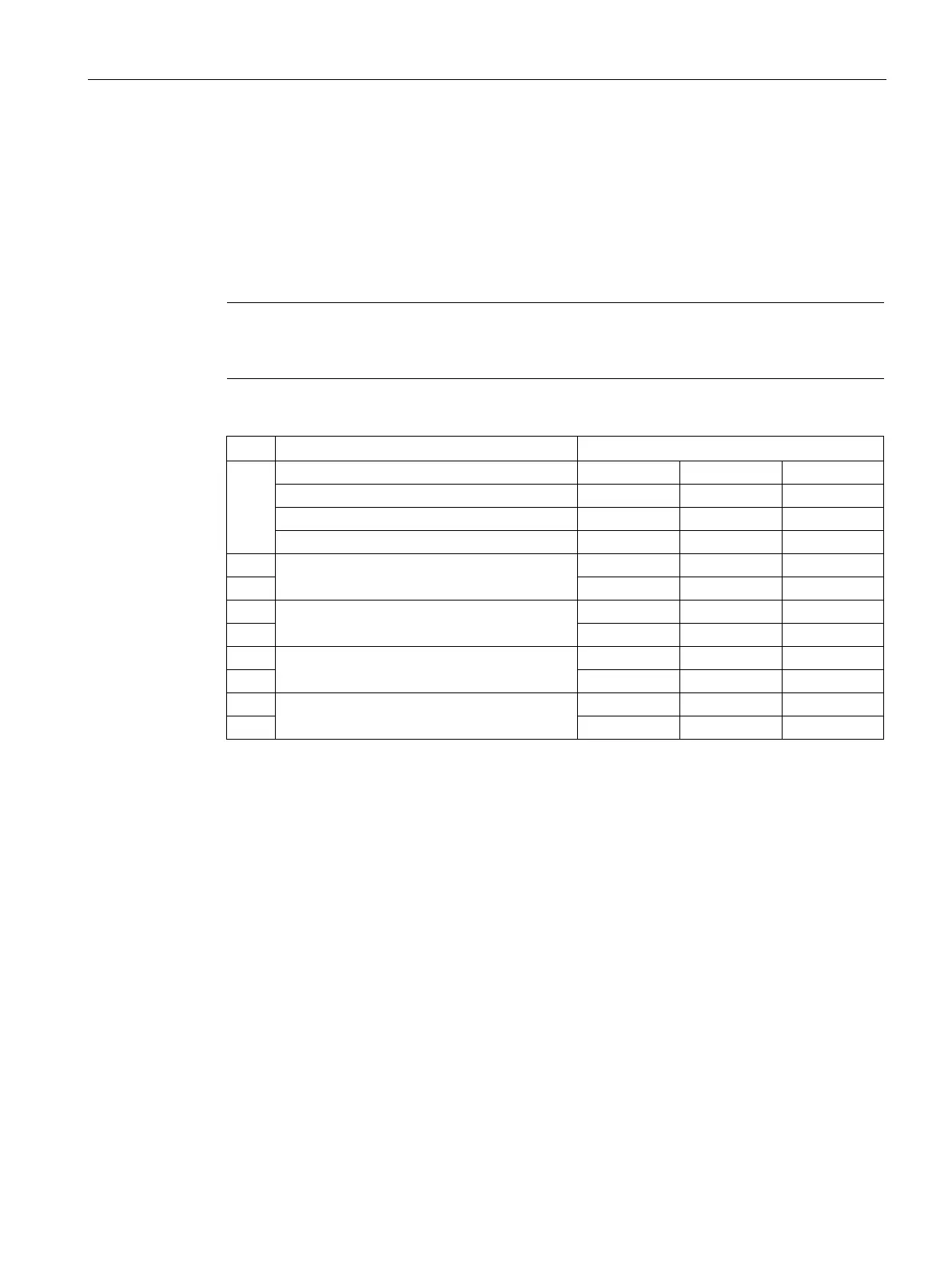
HDEF instruction sets the counting mode
The HDEF instruction assigns HSC counter mode. The following table shows the physical
inputs assigned for clock, direction control, and reset functions. The same input cannot be
used for two different functions, but any input not being used by the present mode of its high-
speed counter can be used for another purpose. For example, if HSC0 is used in mode 1,
which uses I0.0 and I0.4; then I0.1, I0.2, and I0.3 can be used for edge interrupts, HSC3, or
motion control inputs.
Note
All counting modes of HSC0 always use I0.0 and all modes of HSC2 always use I0.2, so
these inputs
are never available for other uses when these counters are in use.
Single-phase counter with internal direction
control
Single-phase counter with external direction
control
Two-phase counter with 2 clock inputs
AB quadrature phase counter

 Loading...


