EasyManuals Logo

Siemens Simatic S7 Series System Manual

Siemens Simatic S7 Series
726 pages
To Next Page IconTo Next Page
To Previous Page IconTo Previous Page
Page #230 background imageLoading...
Page #230 background image
Program instructions
7.6 Counters
S7-200 SMART
230 System Manual, 09/2015, A5E03822230-AC
HSC modes 6 and 7
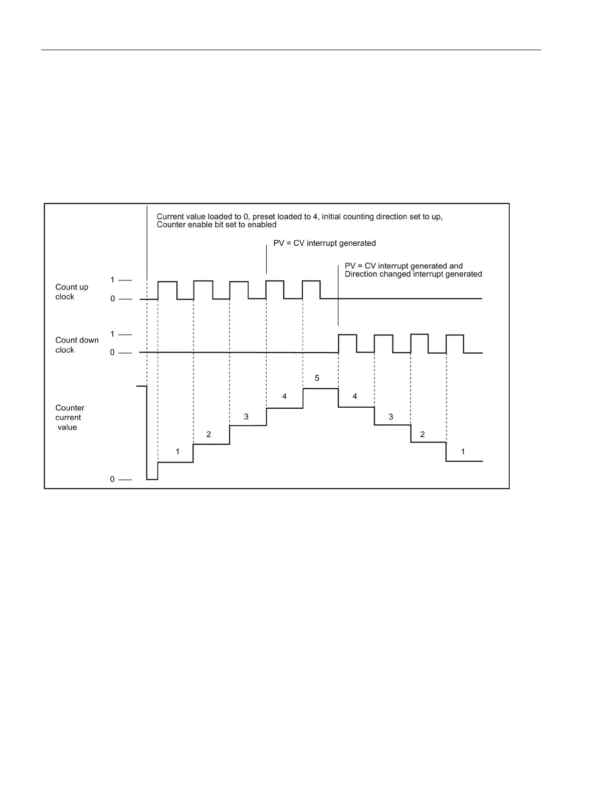
When you use counting modes 6 or 7, and rising edges on both the up clock and down clock
inputs occur within 0.3 microseconds of each other, the high-speed counter could see these
events as happening simultaneously. If this happens, the current value is unchanged and no
change in counting direction is indicated. As long as the separation between rising edges of
the up and down clock inputs is greater than this time period, the high-speed counter
captures each event separately. In either case, no error is generated and the counter
maintains the correct count value.

Table of Contents

Other manuals for Siemens Simatic S7 Series

Questions and Answers:

Question and Answer IconNeed help?

Do you have a question about the Siemens Simatic S7 Series and is the answer not in the manual?

Siemens Simatic S7 Series Specifications

General IconGeneral
CPUVaries by model (e.g., S7-300, S7-400, S7-1200, S7-1500)
Communication InterfacesPROFIBUS, PROFINET, Ethernet, MPI
ProgrammingTIA Portal, STEP 7
Programming LanguagesLAD, FBD, STL, SCL, GRAPH
I/O ModulesDigital, Analog, Specialty modules available
Operating Temperature0°C to 60°C (standard models)
MountingDIN rail mounting
Operating Voltage24V DC or 120/230V AC (varies by model)
Protection ClassIP20 (standard models)
MemoryVaries depending on the S7 model. Includes work memory (RAM) for program execution, load memory (EEPROM or Flash) for program storage, and system memory for operating system functions. Memory sizes range from kilobytes to megabytes.

Related product manuals