EasyManuals Logo

Siemens Simatic S7 Series System Manual

Siemens Simatic S7 Series
726 pages
To Next Page IconTo Next Page
To Previous Page IconTo Previous Page
Page #256 background imageLoading...
Page #256 background image
Program instructions
7.7 Pulse output
S7-200 SMART
256 System Manual, 09/2015, A5E03822230-AC
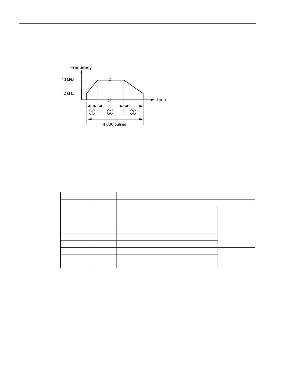
During the acceleration portion of the output profile, the output wave form should reach
maximum pulse frequency in approximately 200 pulses. The output wave form should
complete the deceleration portion of the profile in approximately 400 pulses.
Segment 1: 200 pulses
Segment 2: 3400 pulses
Segment 3: 400 pulses
The following table lists the values for generating the example waveform. The profile table,
for this example, is in V memory and starts at VB500. You can use any block of V memory
that is available for a PTO profile table. You can include instructions in your program to load
these values into V memory, or you can define the values of the profile in the data block.
Table 7- 12 Profile table values
Address
Value
Description
VB500
3
Total number of segments
VD501
2,000
Starting frequency (Hz)
Segment 1
VD505
10,000
Ending frequency (Hz)
VD509
200
Number of pulses
VD513
10,000
Starting frequency (Hz)
Segment 2
VD517
10,000
Ending frequency (Hz)
VD521
3,400
Number of pulses
VD525
10,000
Starting frequency (Hz)
Segment 3
VD529 2,000 Ending frequency (Hz)
VD533
400
Number of pulses
The PTO generator begins by running Segment 1. After the PTO generator reaches the
required number of pulses for Segment 1, it automatically loads Segment 2. This continues
until the last segment. After the number of pulses for the last segment is reached, the
S7-200 SMART CPU disables the PTO generator.
For each segment of the PTO profile, the pulse train begins at the starting frequency
assigned in the table. The PTO generator increases or decreases the frequency at a
constant rate to achieve the ending frequency with the correct number of pulses. However,
the PTO generator limits the frequency to the starting and ending frequencies specified in
the table.

Table of Contents

Other manuals for Siemens Simatic S7 Series

Questions and Answers:

Question and Answer IconNeed help?

Do you have a question about the Siemens Simatic S7 Series and is the answer not in the manual?

Siemens Simatic S7 Series Specifications

General IconGeneral
CPUVaries by model (e.g., S7-300, S7-400, S7-1200, S7-1500)
Communication InterfacesPROFIBUS, PROFINET, Ethernet, MPI
ProgrammingTIA Portal, STEP 7
Programming LanguagesLAD, FBD, STL, SCL, GRAPH
I/O ModulesDigital, Analog, Specialty modules available
Operating Temperature0°C to 60°C (standard models)
MountingDIN rail mounting
Operating Voltage24V DC or 120/230V AC (varies by model)
Protection ClassIP20 (standard models)
MemoryVaries depending on the S7 model. Includes work memory (RAM) for program execution, load memory (EEPROM or Flash) for program storage, and system memory for operating system functions. Memory sizes range from kilobytes to megabytes.

Related product manuals