Program instructions
7.14 Shift and rotate
S7-200 SMART
316 System Manual, 09/2015, A5E03822230-AC
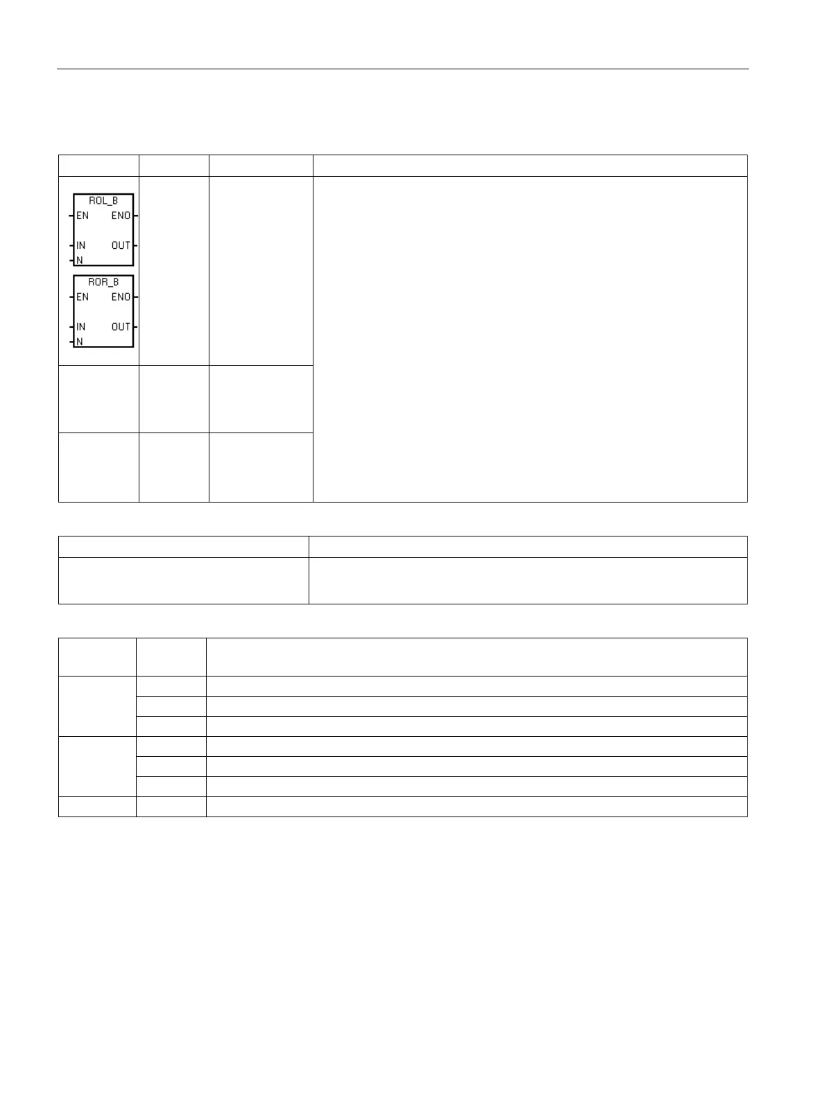
Rotate instructions (only the byte size LAD box is illustrated, the others are similar)
N
N
Rotate left byte
Rotate right byte
The rotate instructions rotate the bit values of input value IN right or left by
the bit position rotate count N and load the result in the memory location
assigned to OUT. The rotate operation is circular.
If the rotate count is greater than or equal to the maximum for the operation
(8 for a byte operation, 16 for a word operation, or 32 for a double-word
operation), the CPU performs a modulo operation on the rotate count to
obtain a valid shift count before the rotation is executed. This result is a shift
count of 0 to 7 for byte operations, 0 to 15 for word operations, and 0 to 31
for double-word operations.
If the rotate count is 0, a rotate operation is not performed. If the rotate oper-
ation is performed, the overflow bit SM1.1 is set to the value of the last bit
rotated out.
If the rotate count is not an integer multiple of 8 (for byte operations), 16 (for
word operations), or 32 (for double-word operations), the last bit value rotat-
ed out is copied to the overflow memory bit SM1.1. The zero memory bit
SM1.0 is set when the value to be rotated is zero.
Byte operations are unsigned. For word and double word operations, the
sign bit is rotated when you use signed data types.
ROL_W
ROR_W
N
Rotate left word
Rotate right
word
ROL_DW
ROR_DW
N
Rotate left dou-
ble word
Rotate right
Non-fatal errors with ENO=0
• 0006H Indirect address • SM1.0 Result of operation = zero
• SM1.1 Overflow (last bit shifted out)
IN
IB, QB, VB, MB, SMB, SB, LB, AC, *VD, *LD, *AC, Constant
IW, QW, VW, MW, SMW, SW, T, C, LW, AC, AIW, *VD, *LD, *AC, Constant
ID, QD, VD, MD, SMD, SD, LD, AC, HC, *VD, *LD, *AC, Constant
OUT
IB, QB, VB, MB, SMB, SB, LB, AC, *VD, *LD, *AC
IW, QW, VW, MW, SMW, SW, T, C, LW, AC, *VD, *LD, *AC
ID, QD, VD, MD, SMD, SD, LD, AC, *VD, *LD, *AC
IB, QB, VB, MB, SMB, SB, LB, AC, *VD, *LD, *AC, Constant

 Loading...


