Program instructions
7.18 Subroutine
S7-200 SMART
350 System Manual, 09/2015, A5E03822230-AC
There are no automatic data type conversions performed on the input or output parameters.
For example, if the variable table specifies that a parameter has the data type REAL, and in
the calling routine a double word (DWORD) is specified for that parameter, the value in the
subroutine will be a double word.
When values are passed to a subroutine, they are placed into the local memory of the
subroutine. The left-most column of the variable table shows the local memory address for
each passed parameter. Input parameter values are copied to the subroutine's local memory
when the subroutine is called. Output parameter values are copied from the subroutine's
local memory to the specified output parameter addresses when the subroutine execution is
complete.
The data element size and type are represented in the coding of the parameters.
Assignment of parameter values to local memory in the subroutine is as follows:
● Parameter values are assigned to local memory in the order specified by the call
subroutine instruction with parameters starting at L 0.0.
● One to eight consecutive bit parameter values are assigned to a single byte starting with
Lx.0 and continuing to Lx.7.
● Byte, word, and double word values are assigned to local memory on byte boundaries
(LBx, LWx, or LDx).
In the Call Subroutine instruction with parameters, parameters must be arranged in order
with input parameters first, followed by input/output parameters, and then followed by output
parameters.
If you are programming in STL, the format of the CALL instruction is:
CALL subroutine number, parameter 1, parameter 2, ... , parameter 16
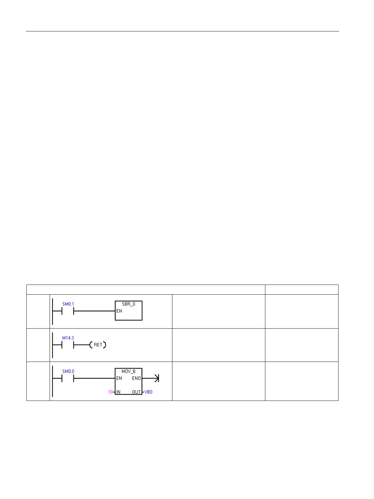
Example: Subroutine and return from subroutine instructions
MAIN
On the first scan, call subroutine 0
for initialization.
LD SM0.1
CALL SBR_0
SBR0
You can use a conditional return to
leave the subroutine before the last
network.
LD M14.3
CRET
SBR0
This network will be skipped if
M14.3 is ON.
LD SM0.0
MOVB 10, VB0

 Loading...


