Communication
8.5 PROFIBUS
S7-200 SMART
System Manual, 09/2015, A5E03822230-AC
385
These SM locations show default values if DP communications have not been established
with a DP master. After a DP master has written parameters and I/O configuration to the
EM DP01 PROFIBUS DP module, these SM locations show the configuration set by the DP
master. You should check the protocol status byte (for example SMB1424 for slot 0) to be
sure that the EM DP01 is currently in data exchange mode with the DP master before using
the information in the SM locations shown in the following table or data in the V memory
buffer.
Note
You cannot configure the EM
DP01 PROFIBUS DP I/O buffer sizes or buffer location by
writing to SM memory locations. Only the DP
master can configure the EM DP01
DP module for DP operation.
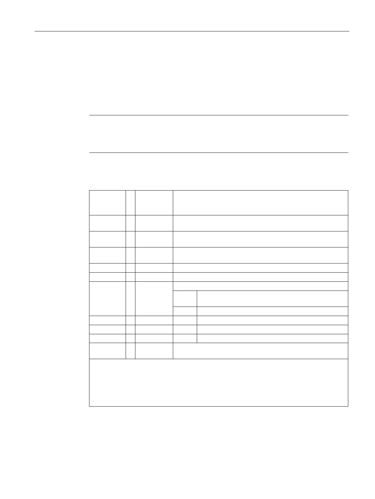
Table 8- 4 Special memory bytes for the EM DP01 PROFIBUS DP
Intelligent
module in
slot 0
Intelligent
module in
slot 5
SMB1400 ... SMB1650 DP device's station address as set by address switches (0 - 99
SMB1401 ... SMB1651 Address of the DP device's master (0 to 126) (displays 255 if no DP
SMW1402 ... SMW1652 V memory address of the output buffer as an offset from VB (for
example, 1000 means VB1000).
Number of bytes of output data
Number of bytes of input data
SMB1406 ... SMB1656
DP standard protocol status byte
Num-
Description
DP communications not initiated since power on
Configuration/parameterization error detected
2 Currently in data exchange mode
Dropped out of data exchange mode
SMB1407 to
... SMB1657 to
Reserved - cleared on power up
Note: SM locations are updated each time the DP device accepts configuration / parameterization
information. These locations are updated even if a configuration/parameterization error is detected.
The locations are cleared on each power up.
Note: This information is also available in the STEP 7-Micro/WIN SMART "PLC information" for the
EM DP01.
Note: The user program can access this information and use it to process the EM DP01 data.

 Loading...


