Libraries
9.3 Modbus library instructions
S7-200 SMART
System Manual, 09/2015, A5E03822230-AC
441
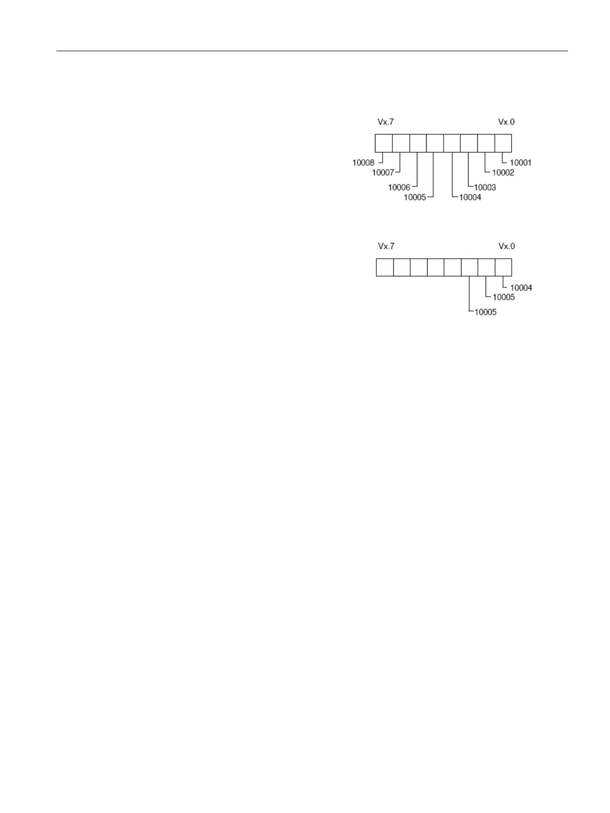
The bit data (addresses 0xxxx and 1xxxx)
areas are read and written as
packed
bytes, that is, 8 bits are packed into each
byte of data. The least significant bit of the
first data byte is the addressed bit number
(the parameter Addr). If only a single bit is
written then the bit must be in the least
significant bit of the by
te pointed to by
Format for Packed Bytes (Discrete Input A
d-
addresses that do not start on
even byte boundaries, the bit correspon
d-
ing to the starting address must be in the
least significant bit of the byte. See the
example of the packed byte format for 3
bits starting at Modbus address 10004.
Format for Packed Bytes (Discrete input starting
at address 10004)
When writing to the discrete output data type (coils), the user is responsible for placing the
bits in the correct bit positions within the packed byte before the data is passed to the
MBUS_MSG instruction via the DataPtr.
The Done output is OFF while a request is being sent and the response is being received.
The Done output is ON when the response is complete or when the MBUS_MSG instruction
was aborted because of an error.
The Error output is valid only when the Done output is ON.
Modbus master execution error codes (Page 442)

 Loading...


