Libraries
9.3 Modbus library instructions
S7-200 SMART
444 System Manual, 09/2015, A5E03822230-AC
3. Place only one MBUS_SLAVE instruction in your program. This instruction should be
called every scan to service any requests that have been received.
4. Connect a communications cable between the S7-200 SMART CPU port you assigned
with the MBUS_INIT port parameter and the Modbus master device.
Avoiding unwanted current flow
Interconnecting equipment with different reference potentials can cause unwanted
currents to flow through the interconnecting cable. These unwanted currents can cause
communications errors or damage equipment.
Ensure that all equipment that is connected with a communications cable either shares
a common circuit reference or is isolated to prevent unwanted current flows.
The accumulators (AC0, AC1, AC2, AC3) are used by the Modbus slave instructions and
appear in the Cross Reference listing. Prior to execution, the values in the accumulators of a
Modbus slave instruction are saved and restored to the accumulators before the Modbus
slave instruction is complete, ensuring that all user data in the accumulators is preserved
while executing a Modbus slave instruction.
The Modbus slave instructions support the Modbus RTU protocol. These instructions use the
Freeport feature of the S7-200 SMART CPU to support the most common Modbus functions.
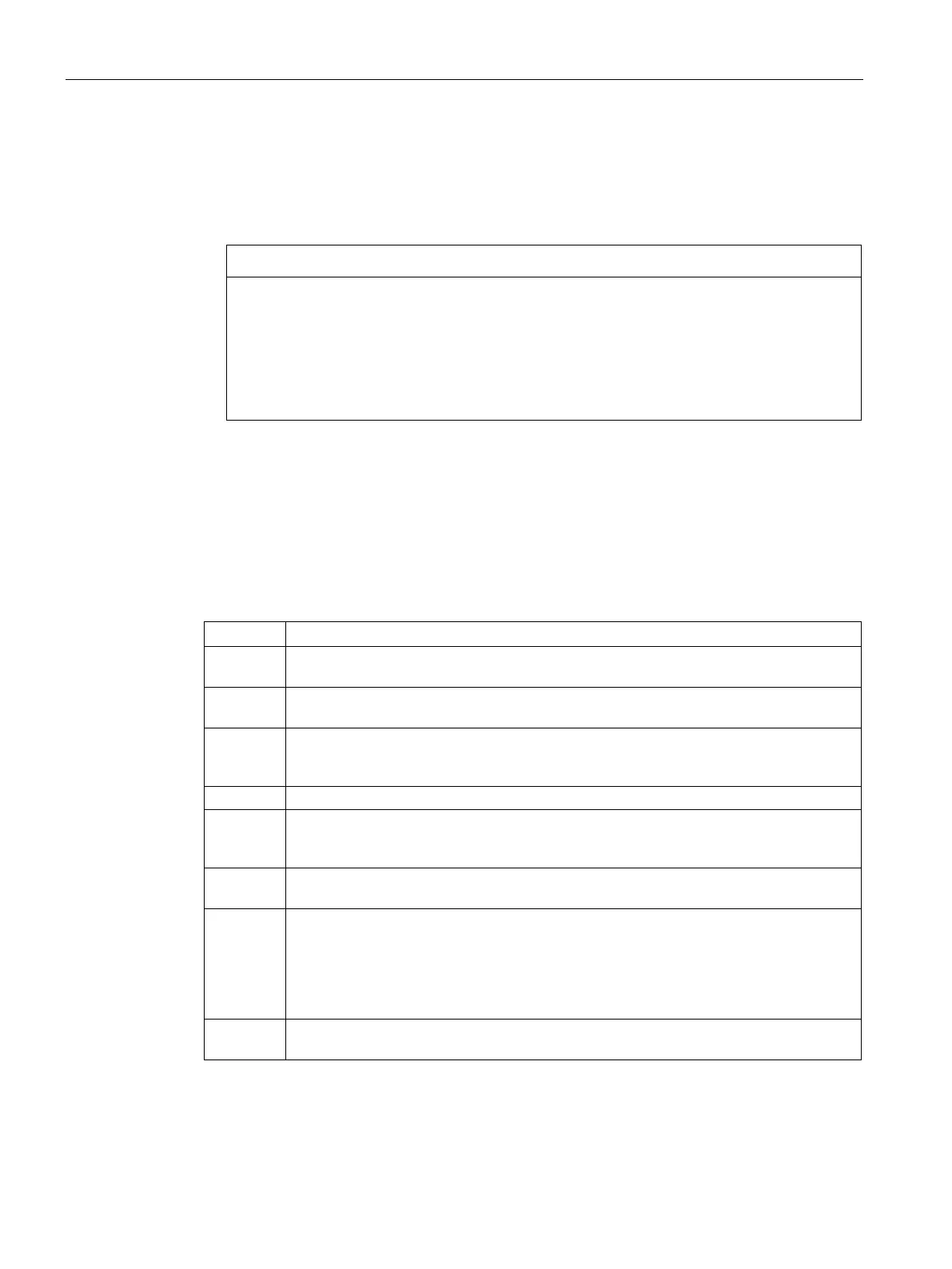
The following Modbus functions are supported:
1 Read single/multiple coil (discrete output) status. Function 1 returns the on/off status of
any number of output points (Qs).
2 Read single/multiple contact (discrete input) status. Function 2 returns the on/off status
of any number of input points (Is).
3 Read single/multiple holding registers. Function 3 returns the contents of V memory.
Holding registers are word values under Modbus and allow you to read up to 120 words
Read single/multiple input registers. Function 4 returns analog Input values.
5 Write single coil (discrete output). Function 5 sets a discrete output point to the specified
value. The point is not forced and the program can overwrite the value written by the
6 Write single holding register. Function 6 writes a single holding register value to the V
memory of the S7-200 SMART.
15 Write multiple coils (discrete outputs). Function 15 writes the discrete output values to
the Q image register of the S7-200 SMART. The starting output point must begin on a
byte boundary (for example, Q0.0 or Q2.0) and the number of outputs written must be a
multiple of eight. This is a restriction for the Modbus slave protocol instructions. The
points are not forced and the program can overwrite the values written by the Modbus
16 Write multiple holding registers. Function 16 writes multiple holding registers to the V
memory of the S7-200 SMART. There can be up to 120 words written in one request.

 Loading...


