Libraries
9.3 Modbus library instructions
S7-200 SMART
System Manual, 09/2015, A5E03822230-AC
449
The following program turns on outputs Q0.1 and Q0.2 if there is an error returned from the
MBUS_MSG instruction.
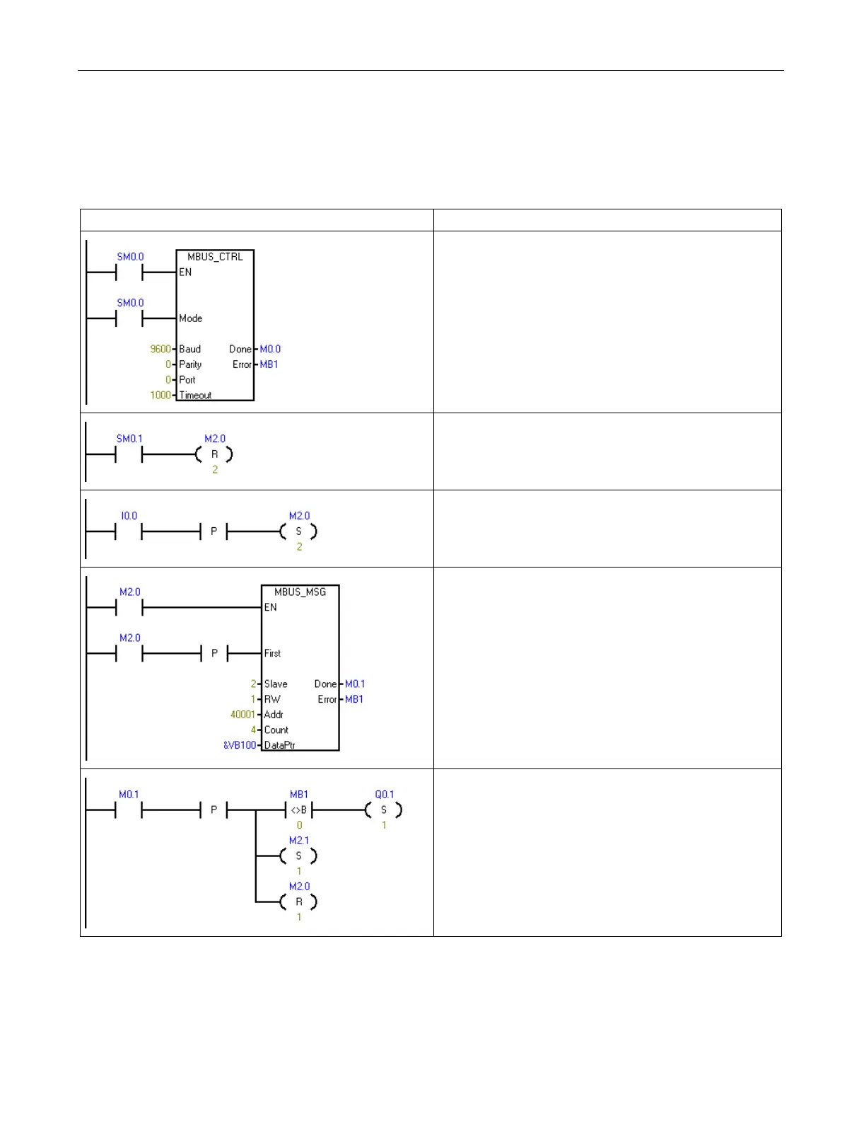
Table 9- 33 Example Modbus master program
Network 1:
Initialize and monitor the Modbus master by calling
MBUS_CTRL on every scan. The Modbus master is set for
9600 baud and no parity. The slave device is allowed 1000
milliseconds (1 second) to respond.
Network 2
On the first scan, reset the enable flags (M2.0 and M2.1)
used for the two MBUS_MSG instructions.
Network 3
When I0.0 changes from OFF to ON, set the enable flag for
the first MBUS_MSG instruction (M2.0).
Network 4
Call the MBUS_MSG instruction when the first enable flag
(M2.0) is ON. The First parameter must be set for only the
first scan that the instruction is enabled.
This instruction writes (RW = 1) 4 holding registers to
slave 2. The write data is taken from VB100-VB107
(4 words) in the CPU and written to address 40001 - 40004
in the Modbus slave.
Network 5
When the first MBUS_MSG instruction is complete
(Done goes from 0 to 1), clear the enable for the first
MBUS_MSG and set the enable for the second
MBUS_MSG instruction.
If Error (MB1) is not zero, then set Q0.1 to show the error.

 Loading...


