Open loop motion control
12.5 Configuring an Axis of Motion
S7-200 SMART
System Manual, 09/2015, A5E03822230-AC
503
5. The Axis of Motion provides a reference point switch (RPS) input that is used when
seeking the RP. The RP is identified by a method of locating an exact position with
respect to the RPS. The RP can be centered in the RPS Active zone, the RP can be
located on the edge of the RPS Active zone, or the RP can be located a specified number
of zero pulse (ZP) input transitions from the edge of the RPS Active zone.
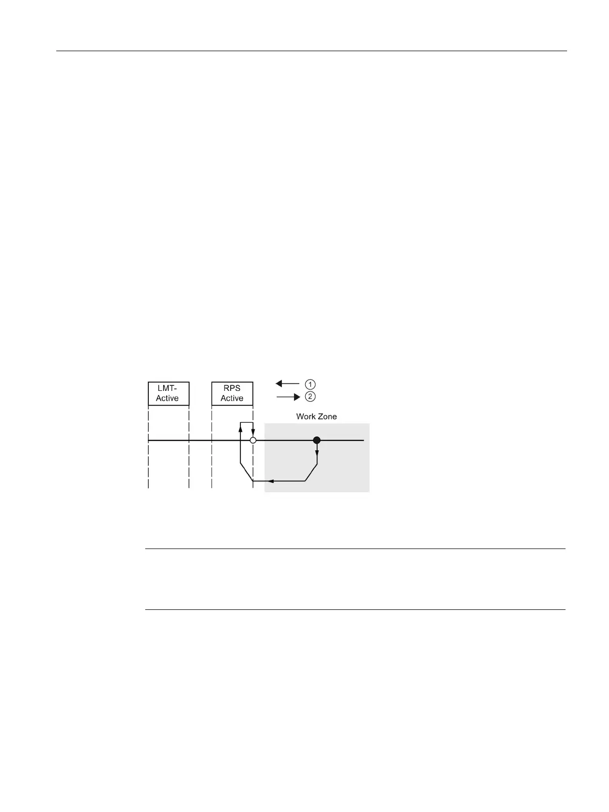
6. You can configure the sequence that the Axis of Motion uses to search for the reference
point. The following figure shows a simplified diagram of the default RP search sequence.
Select one of the following options for the RP search sequence:
–
: Does not perform a RP seek sequence
–
: The RP is where the RPS input goes active on the approach from
the work zone side. (Default)
–
: The RP is centered within the active region of the RPS input.
–
: The RP is located outside the active region of the RPS input.
RP_Z_CNT specifies how many ZP (Zero Pulse) input counts should be received after
the RPS becomes inactive.
–
: The RP is generally within the active region of the RPS input.
RP_Z_CNT specifies how many ZP (Zero Pulse) input counts should be received after
the RPS becomes active.
Figure 12-1 ①: RP seek direction
②: RP approach direction
Note
The RPS Active region (which is the distance that the RPS
input remains active) must be
greater than the distance required to decelerate from the RP_FAST speed to the RP_SLOW
speed. If the distance is too short, the Axis of Motion generates an error.

 Loading...


