Installation
3.4 Wiring guidelines
S7-200 SMART
52 System Manual, 09/2015, A5E03822230-AC
Guidelines for inductive loads
You should equip inductive loads with suppression circuits to limit voltage rise when the
control output turns off. Suppression circuits protect your outputs from premature failure due
to the high voltages associated with turning off inductive loads. In addition, suppression
circuits limit the electrical noise generated when switching inductive loads. Placing an
external suppression circuit so that it is electrically across the load, and physically located
near the load is most effective in reducing electrical noise.
The DC (transistor) outputs include internal suppression circuits that are adequate for the
inductive loads in most applications. Since the relay output contacts can be used to switch
either a DC or an AC load, internal protection is not provided.
effectiveness of a given suppression circuit depends on the application, and you must
verify it for your particular use. Always ensure that all components used in your suppression
circuit are rated for use in the application.
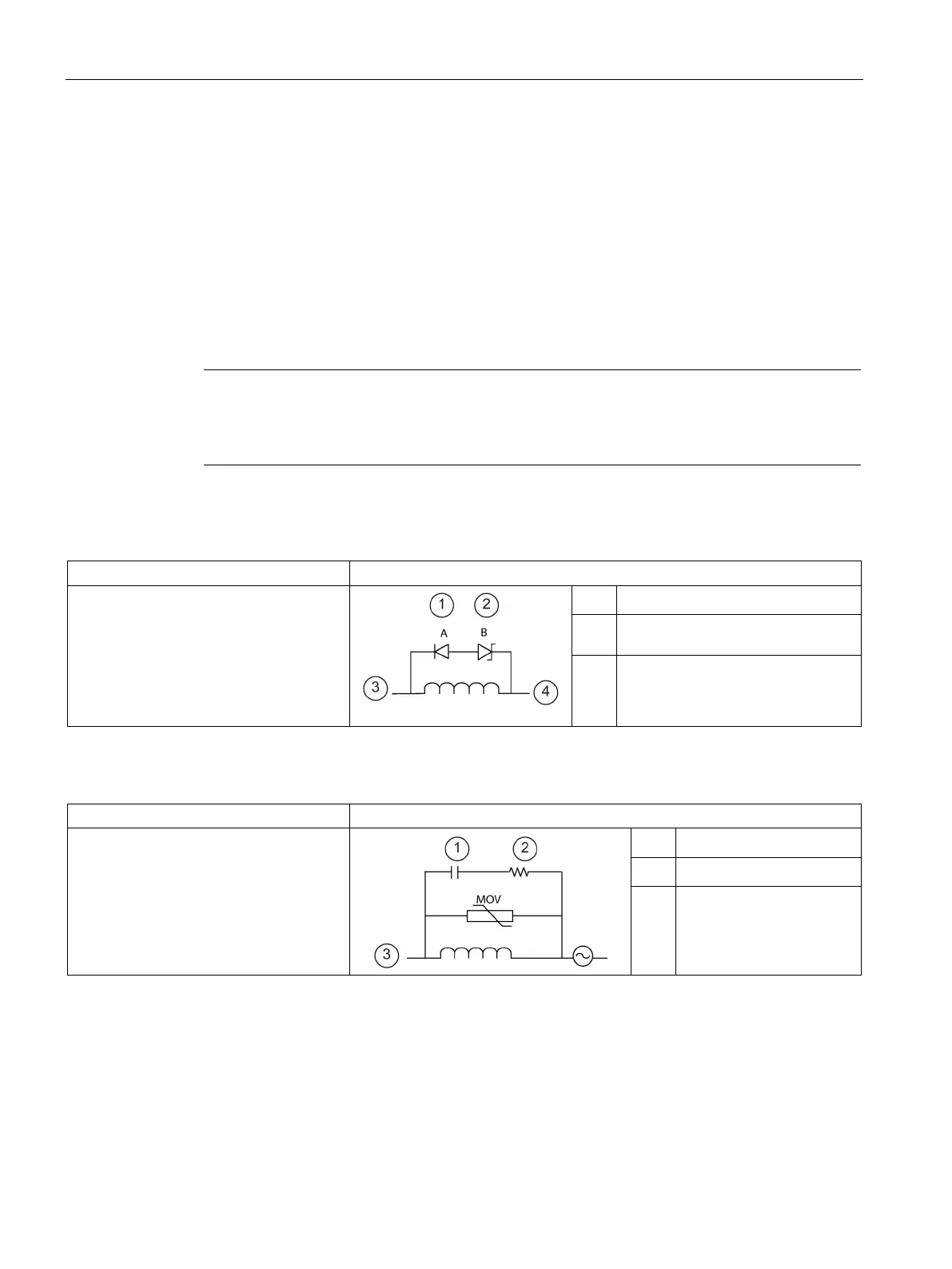
Table 3- 9 Typical suppressor circuit for DC or relay outputs that switch DC inductive loads
In most applications, the addition of a
diode ① across a DC inductive load is
suitable, but if your application requires
faster turn-off times, then the addition of a
Zener diode
② is recommended. Be sure
to size your Zener diode properly for the
amount of current in your output circuit.
1N4001 diode or equivalent
8.2 V Zener (DC outputs),
36 V Zener (Relay outputs)
③
Output point
Table 3- 10 Typical suppressor circuit for relay outputs that switch AC inductive loads
When you use a relay output to switch
115 V/230 V AC loads, place the appro-
priately rated resistor-capacitor-metal
oxide varistor (MOV) circuit across the AC
load. Ensure that the working voltage of
the MOV is at least 20% greater than the
nominal line voltage.
0.1 μ F
100 to 120 Ω
③
Output point

 Loading...


