Open loop motion control
12.8 Axis of Motion example programs
S7-200 SMART
532 System Manual, 09/2015, A5E03822230-AC
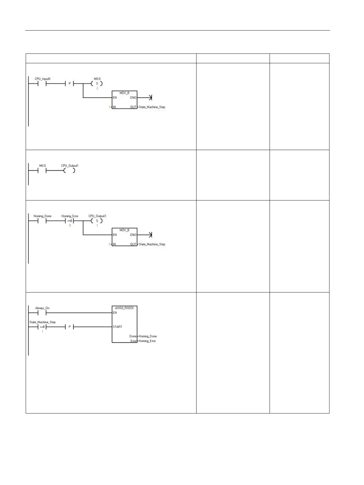
Network 4
Start the process. When
CPU_Input0 is toggled from
off to on, the
State_Machine_Step is set
to "1".
Symbol and Address:
1
• CPU_Input0 = I0.0
• State_Machine_Step =
VB1500
EU
S M0.0, 2
MOVB 1,
State_Machine_
Step
Network 5
This network turns
CPU_Input1 on.
Symbol and Address:
1
• CPU_Input1 = I0.1
= CPU_Input1
Network 6
When the homing is com-
plete, move to the next
step.
Symbol and Address:
1
• CPU_Output3 = Q0.3
• Homing_Done = M1.1
• Homing_Error = VB930
• State_Machine_Step =
VB1500
AB= Homing_Error
S CPU_Output3
MOVB 2,
State_Machine_
Step
Network 7
When the state machine is
in Step 1, the system auto-
matically homes the axis. If
there is a Homing error, the
Homing_Error output dis-
plays the error code.
Symbol and Address:
1
• Always_On = SM0.0
• AXIS0_RSEEK = SBR5
• Homing_Done = M1.1
• Homing_Error = VB930
• State_Machine_Step =
VB1500
= L60.0
LDB
State_Machine_
Step, 1
EU
= L63.7
LD L60.0
CALL
AXIS0_RSEEK,
L63.7,
Homing_Done,
Homing_Error

 Loading...


