Open loop motion control
12.8 Axis of Motion example programs
S7-200 SMART
534 System Manual, 09/2015, A5E03822230-AC
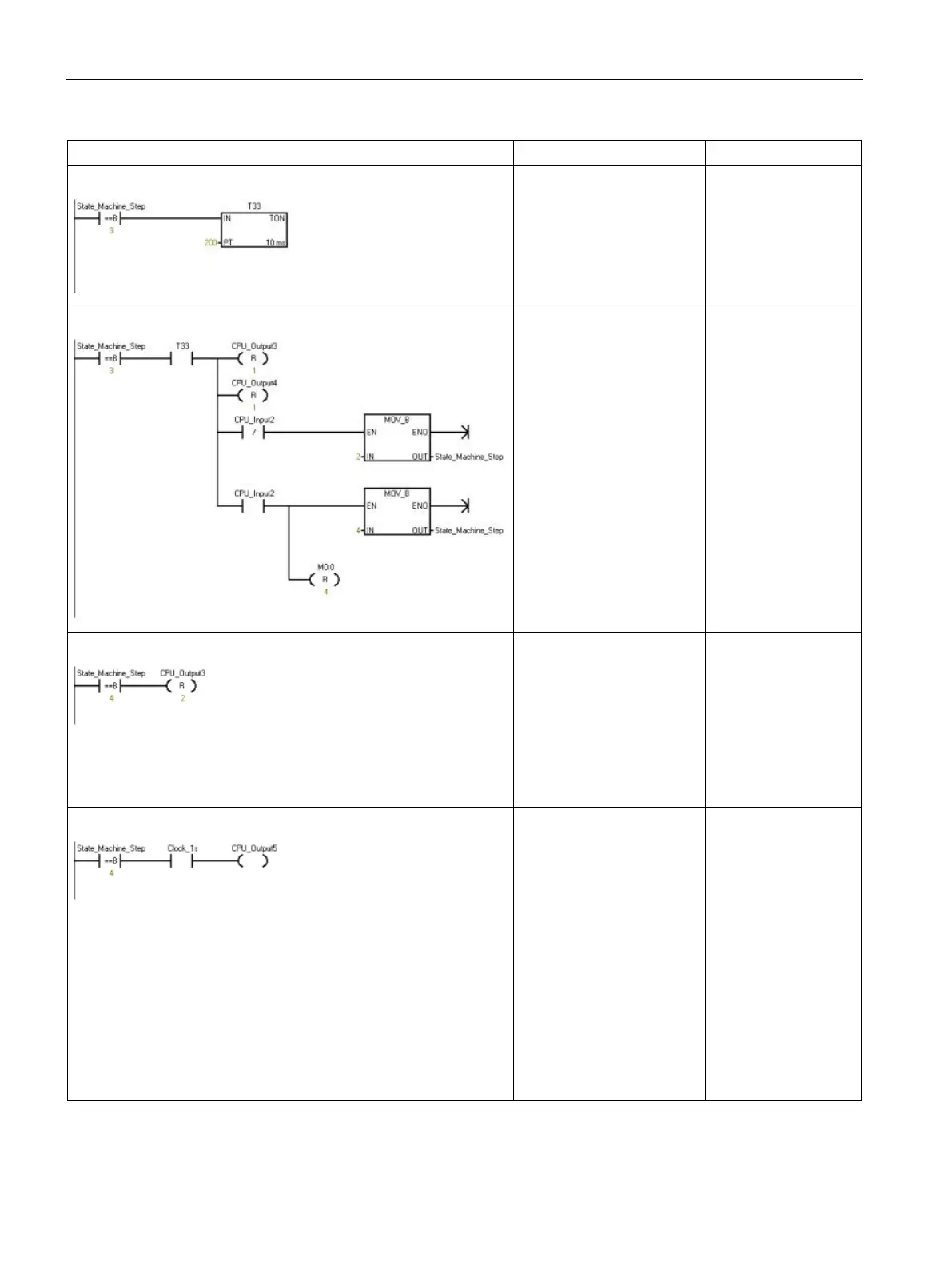
Network 10
Wait for Step 3.
Symbol and Address:
1
• State_Machine_Step =
VB1500
State_Machine_
Step, 3
TON T33, 200
Network 11
If the State Machine moves
to Step 3, wait for 2 s. Then,
evaluate the status of the
switches, and restart the
move or stop.
Symbol and Address:
1
• CPU_Input2 = I0.2
• CPU_Output3 = Q0.3
• CPU_Output4 = Q0.4
• State_Machine_Step =
VB1500
State_Machine_
Step, 3
A T33
LPS
R CPU_Output3, 1
R CPU_Output4, 1
AN CPU_Input2
MOVB 2,
State_Machine_
Step
LPP
A CPU_Input2
MOVB 4,
State_Machine_
Step
Network 12
If the State Machine moves
to Step 4, clear the outputs.
Symbol and Address:
1
• CPU_Output3 = Q0.3
• State_Machine_Step =
VB1500
State_Machine_
Step, 4
R CPU_Output3, 2
Network 13
If the State Machine is in
Step 4, flash output 5 to
indicate an error.
Symbol and Address:
1
• Clock_1s = SM0.5
(Clock pulse that is ON
for 0.5 s and OFF for 0.5
s for a duty cycle time of
1 s.)
• CPU_Output5 = Q0.5
• State_Machine_Step =
VB1500
State_Machine_
Step, 4
A Clock_1s
= CPU_Output5

 Loading...


