Open loop motion control
12.10 Advanced topics
S7-200 SMART
554 System Manual, 09/2015, A5E03822230-AC
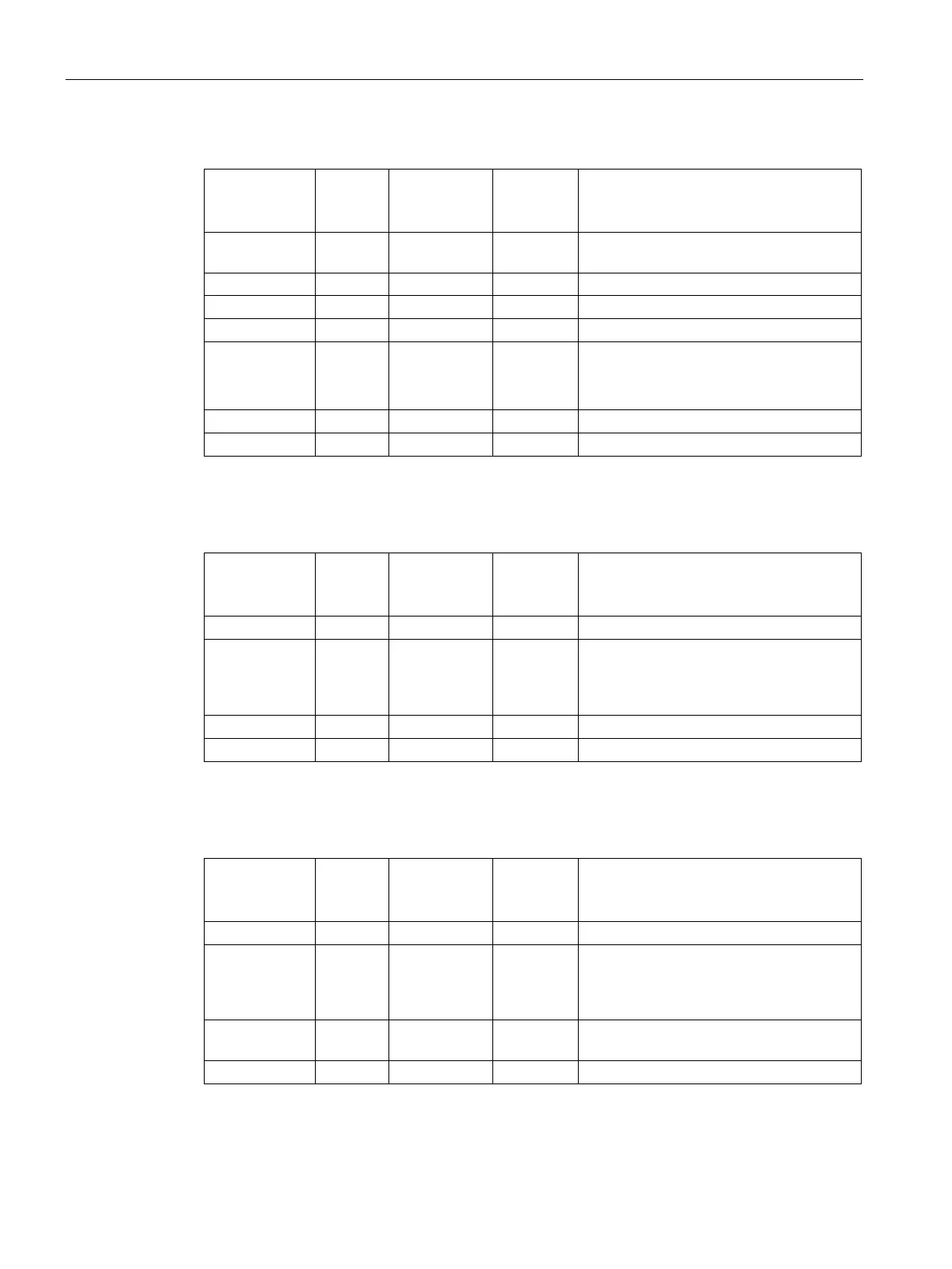
Table 12- 43 Profile detail for Mode 1 (Relative position)
Byte offset
from start of
profile
+0 STEPS byte n = Number of steps configured in this
+1 MODE byte 0 = Relative position
Distance to travel in step 0
●
●
Distance to travel in step n
Table 12- 44 Profile detail for Mode 2 (Single-speed, continuous positive rotation) and Mode 3 (Single-
speed, continuous negative rotation)
Byte offset
from start of
profile
+1 MODE byte 2= Single-speed, continuous positive
rotation or
3 = Single-speed, continuous negative
Table 12- 45 Profile detail for Mode 6 (Single-speed, continuous positive rotation with triggered stop)
and Mode 7 (Single-speed, continuous negative rotation with triggered stop)
Byte offset
from start of
profile
+1 MODE byte 6 = Single-speed, continuous positive
rotation with triggered stop or
7 = Single-speed, continuous negative
rotation with triggered stop
+2 0 POS dint/fp Distance to travel after activation of RPS
signal (value must be positive)
+6 SPEED dint/fp Target speed

 Loading...


