Technical specifications
A.2 S7-200 SMART CPUs
S7-200 SMART
System Manual, 09/2015, A5E03822230-AC
581
All other inputs:
• Shielded: 500 m normal inputs
• Unshielded: 300 m normal inputs
1
1
When I0.0 to I0.3 are used at high-speed counter inputs, all other inputs must use shielded cable.
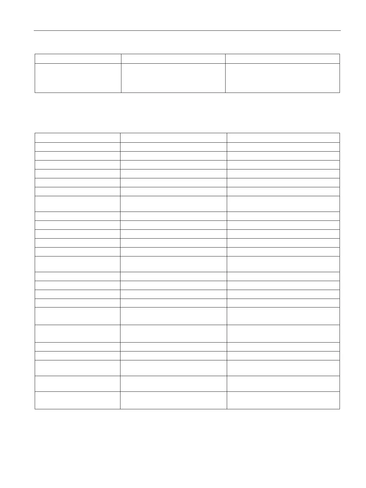
Table A- 29 Digital outputs
Type Solid state - MOSFET (sourcing) Relay, dry contact
5 to 30 V DC or 5 to 250 V AC
Logic 1 signal at max. current
Logic 0 signal with 10 KΩ load
Rated current per point (max.)
Rated current per common
6 A 10.0 A
Leakage current per point
Isolation (field side to logic) 500 V AC for 1 minute 1500 V AC for 1 minute (coil to contact)
Isolation between open contacts
L+ minus 48 V DC, 1 W dissipation
Switching delay (Qa.0 to Qa.3) 1.0 μs max., off to on
10 ms max.
Switching delay (Qa.4 to Qb.7) 50 μs max., off to on,
200 μs max., on to off
10 ms max.
Lifetime mechanical (no load)
10,000,000 open/close cycles
Lifetime contacts at rated load
100,000 open/close cycles
Output state in STOP mode Last value or substitute value (default
Last value or substitute value (default value
Number of outputs on simulta-
12 12
Cable length (max.), in meters Shielded: 500 m
Shielded: 500 m

 Loading...


