Technical specifications
A.3 Digital inputs and outputs expansion modules (EMs)
S7-200 SMART
608 System Manual, 09/2015, A5E03822230-AC
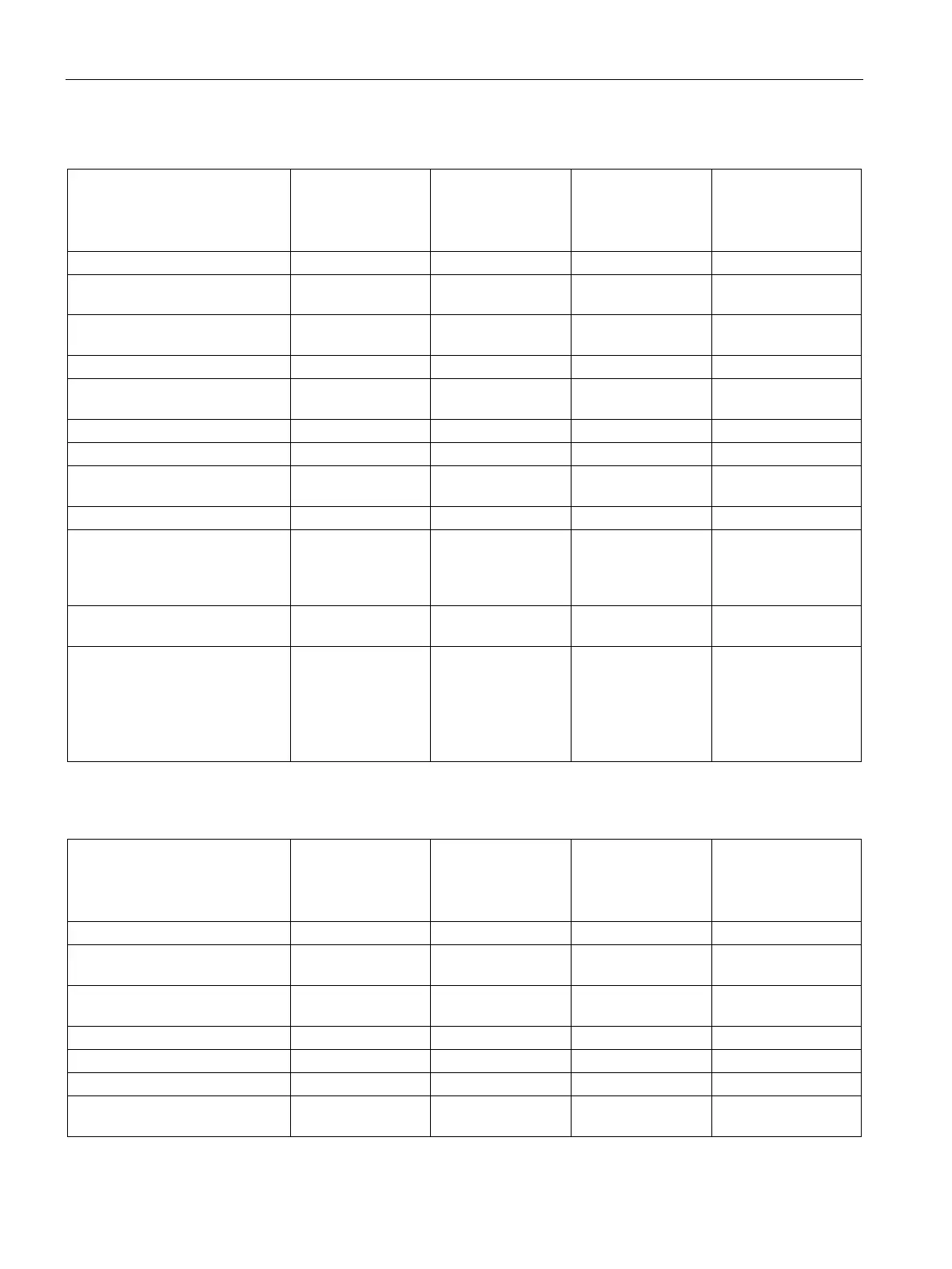
Table A- 75 Digital inputs
EM Digital
8 x Inputs/
Digital 8 x Outputs
(EM DT16)
EM Digital
8 x Inputs/
8 x Relay Outputs
(EM DR16)
EM Digital
16 x Inputs/ Digital
16 x Outputs
(EM DT32)
EM Digital
16 x Inputs /
16 x Relay Outputs
(EM DR32)
Type Sink/Source (IEC
Type 1 sink)
SinkSource (IEC
Type 1 sink)
Sink/Source (IEC
Type 1 sink)
Sink/Source (IEC
Type 1 sink)
Rated voltage 24 V DC at 4 mA,
24 V DC at 4 mA,
24 V DC at 4 mA,
24 V DC at 4 mA,
Continuous permissible voltage
Surge voltage 35 V DC for 0.5
35 V DC for 0.5
35 V DC for 0.5
35 V DC for 0.5 sec.
Isolation (field side to logic) 500 V AC for 1
500 V AC for 1
500 V AC for 1
500 V AC for 1 mi-
Filter times 0.2, 0.4, 0.8, 1.6,
3.2, 6.4, and 12.8
ms, selectable in
0.2, 0.4, 0.8, 1.6,
3.2, 6.4, and 12.8
ms, selectable in
0.2, 0.4, 0.8, 1.6,
3.2, 6.4, and 12.8
ms, selectable in
0.2, 0.4, 0.8, 1.6, 3.2,
6.4, and 12.8 ms,
selectable in groups
Number of inputs on simultane-
8 8 16 16
Cable length (max.), in meters Shielded:
500 m normal in-
puts
Unshielded:
300 m normal in-
Shielded:
500 m normal in-
puts
Unshielded:
300 m normal in-
Shielded:
500 m normal in-
puts
Unshielded:
300 m normal in-
Shielded:
500 m normal inputs
Unshielded:
300 m normal inputs
Table A- 76 Digital outputs
EM Digital
8 x Inputs/
Digital 8 x Outputs
(EM DT16)
EM Digital
8 x Inputs/
8 x Relay Outputs
(EM DR16)
EM Digital
16 x Inputs/ Digital
16 x Outputs
(EM DT32)
EM Digital
16 x Inputs/
16 x Relay Outputs
(EM DR32)
Number of outputs 8 8 16 16
Type Solid state-
Relay, dry contact Solid state-
Relay, dry contact
Voltage range 20.4 to 28.8 V DC 5 to 30 V DC or
20.4 to 28.8 V DC 5 to 30 V DC or
Logic 1 signal at max. current
Logic 0 signal with 10 KΩ load
Rated current per point (max.)
Rated current per common
3 A 8 A 6 A 8 A

 Loading...


