Technical specifications
A.4 Analog inputs and outputs expansion modules (EMs)
S7-200 SMART
System Manual, 09/2015, A5E03822230-AC
615
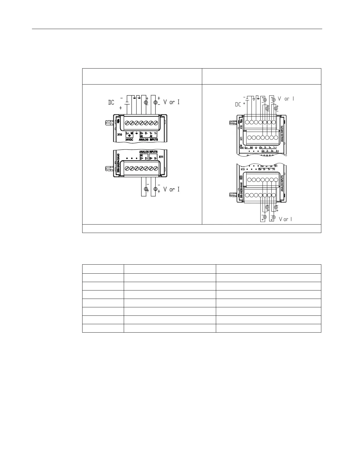
Table A- 86 Wiring diagram EM AE04 Analog 4 x Inputs (6ES7 288-3AE04-0AA0) and EM AE08 An-
alog 8 x Inputs (6ES7 288-3AE08-0AA0
EM AE04 Analog 4 x Inputs
(6ES7 288-3AE04-0AA0)
EM AE08 Analog 8 x Inputs
(6ES7 288-3AE08-0AA0)
Note: Connectors must be gold. See Appendix F, Spare parts and other hardware, for article number.
Table A- 87 Connector pin locations for EM AE04 Analog 4 x Inputs (6ES7 288-3AE04-0AA0)
7 AI 1- AI 3-

 Loading...


