Technical specifications
A.5 Thermocouple and RTD expansion modules (EMs)
S7-200 SMART
628 System Manual, 09/2015, A5E03822230-AC
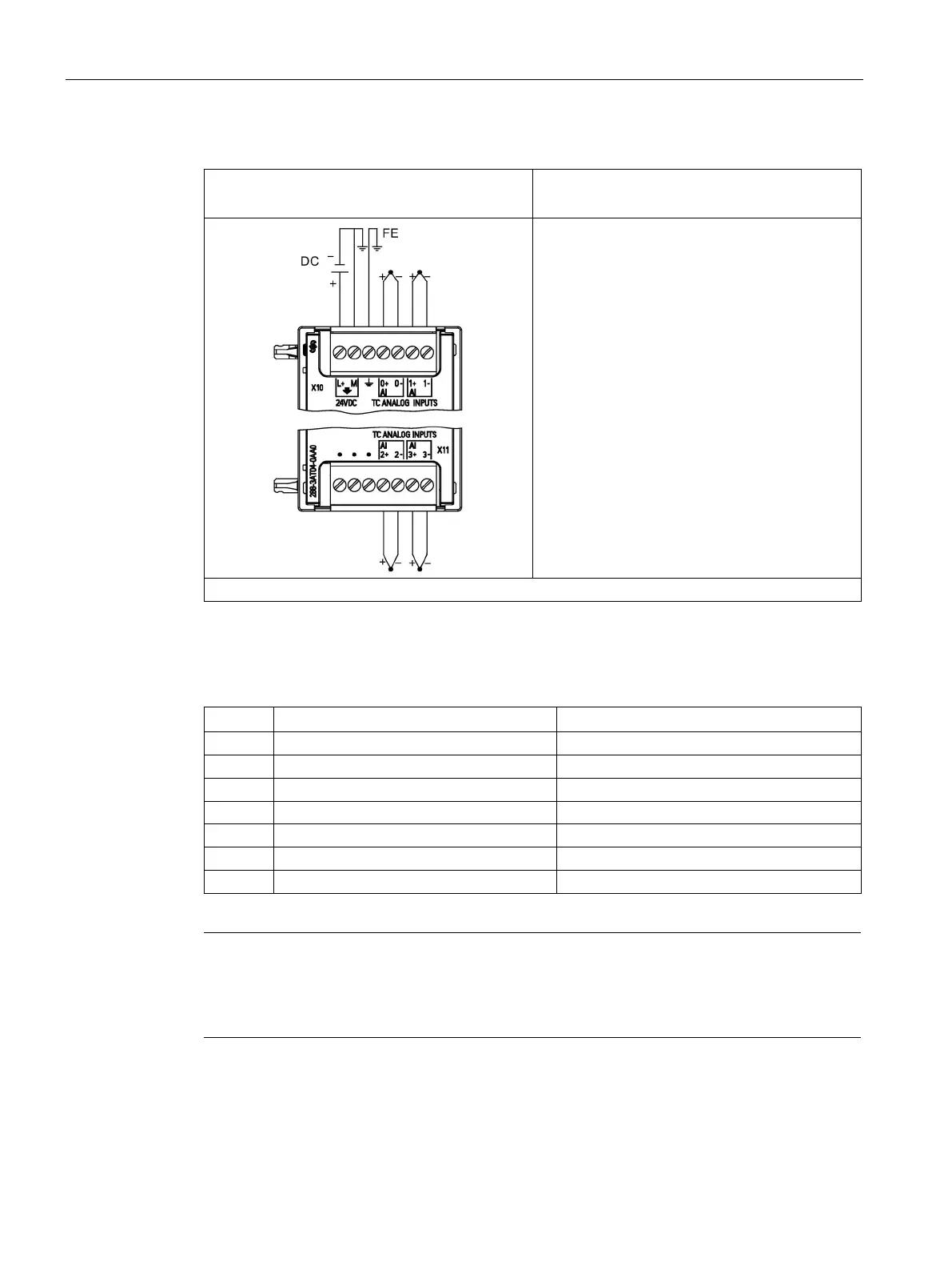
Table A- 111 Wiring diagram for the EM AT04 Thermocouple 4 x 16 bit (6ES7 288-3AT04-0AA0)
EM AT04 4 x 16 bit
(6ES7 288-3AT04-0AA0)
Note: Connectors must be gold. See Appendix F, Spare Parts and other hardware for article number.
① TC 2, 3, 4, and 5 not shown connected for clarity.
Table A- 112 Connector pin locations for EM AT04 4 x 16 bit (6ES7 288-3AT04-0AA0)
4 AI 0+ /TC AI 2+ /TC
6 AI 1+ /TC AI 3+ /TC
Note
Unused analog inputs should be shorted.
The thermocouple unused channels can be deactivated. No error will occur if an unused
channel is deactivated.

 Loading...


