EasyManuals Logo

Siemens Simatic S7 Series System Manual

Siemens Simatic S7 Series
726 pages
To Next Page IconTo Next Page
To Previous Page IconTo Previous Page
Page #639 background imageLoading...
Page #639 background image
Technical specifications
A.6 Digital signal boards
S7-200 SMART
System Manual, 09/2015, A5E03822230-AC
639
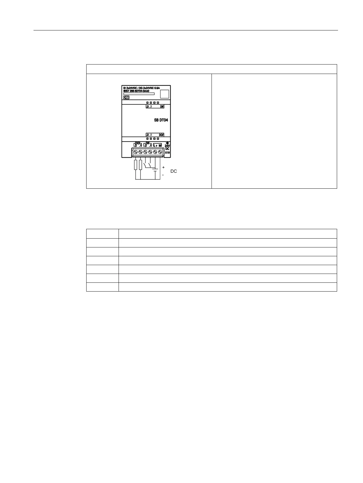
Table A- 128 Wiring diagram for the SB DT04 2 Digital Input/2 Digital Output (6ES7 288-5DT04-0AA0)
SB DT04 2 Digital Input/2 Digital Output (6ES7 288-5DT04-0AA0)
Table A- 129 Connector pin locations for SB DT04 2 Digital Input/2 Digital Output (6ES7 288-5DT04-
0AA0)
Pin
X19
1
DQ f.0
2
DQ f.1
3
DI f.0
4
DI f.1
5
L+ / 24 V DC
6
M / 24 V DC

Table of Contents

Other manuals for Siemens Simatic S7 Series

Questions and Answers:

Question and Answer IconNeed help?

Do you have a question about the Siemens Simatic S7 Series and is the answer not in the manual?

Siemens Simatic S7 Series Specifications

General IconGeneral
CPUVaries by model (e.g., S7-300, S7-400, S7-1200, S7-1500)
Communication InterfacesPROFIBUS, PROFINET, Ethernet, MPI
ProgrammingTIA Portal, STEP 7
Programming LanguagesLAD, FBD, STL, SCL, GRAPH
I/O ModulesDigital, Analog, Specialty modules available
Operating Temperature0°C to 60°C (standard models)
MountingDIN rail mounting
Operating Voltage24V DC or 120/230V AC (varies by model)
Protection ClassIP20 (standard models)
MemoryVaries depending on the S7 model. Includes work memory (RAM) for program execution, load memory (EEPROM or Flash) for program storage, and system memory for operating system functions. Memory sizes range from kilobytes to megabytes.

Related product manuals