Technical specifications
A.7 Analog signal boards
S7-200 SMART
System Manual, 09/2015, A5E03822230-AC
641
SB Analog 1 x input (SB AE01)
Isolation (field side to logic)
Cable length (meters) 100 m twisted and shielded
Table A- 132 Diagnostics
SB Analog 1 x input (SB AE01)
24 VDC low voltage None
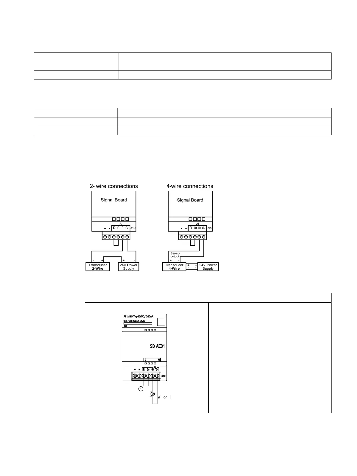
SB AE01 wiring current transducers
Wiring current transducers are available as 2-wire transducers and 4-wire transducers as
shown below.
Table A- 133 Wiring diagram for the SB AE01 Analog 1 x Input (6ES7 288-5AE01-0AA0)
SB AE01 - SB Analog Input 1 x Input (6ES7 288-5AE01-0AA0)
① Connect "R" and "0+" for current applications.
Note: Connectors must be gold. See Appendix F,
Spare parts and other hardware for article num-
ber.

 Loading...


