EasyManuals Logo

Siemens Simatic S7 Series System Manual

Siemens Simatic S7 Series
726 pages
To Next Page IconTo Next Page
To Previous Page IconTo Previous Page
Page #647 background imageLoading...
Page #647 background image
Technical specifications
A.9 Battery board signal boards (SBs)
S7-200 SMART
System Manual, 09/2015, A5E03822230-AC
647
Diagnostics
SB BA01 Battery Board
Critical battery level
< 2.5 V
Battery diagnostic Low voltage indicator:
Low battery voltage causes the LED on the BA01 panel
to illuminate with the red light continuously ON.
Diagnostic alarm and/or digital output status of battery
low condition available
Battery status Battery status bit provided
0 = Battery OK
1 = Battery low
Battery status update Battery status is updated at power up and then once per day
while CPU is in RUN mode.
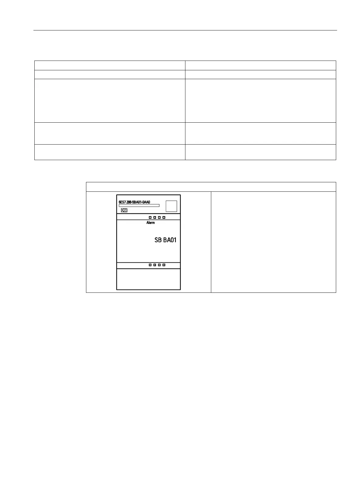
Table A- 146 Wiring diagram for the SB BA01 Battery board (6ES7 288-5BA01-0AA0)
SB BA01 Battery board (6ES7 288-5BA01-0AA0)

Table of Contents

Other manuals for Siemens Simatic S7 Series

Questions and Answers:

Question and Answer IconNeed help?

Do you have a question about the Siemens Simatic S7 Series and is the answer not in the manual?

Siemens Simatic S7 Series Specifications

General IconGeneral
CPUVaries by model (e.g., S7-300, S7-400, S7-1200, S7-1500)
Communication InterfacesPROFIBUS, PROFINET, Ethernet, MPI
ProgrammingTIA Portal, STEP 7
Programming LanguagesLAD, FBD, STL, SCL, GRAPH
I/O ModulesDigital, Analog, Specialty modules available
Operating Temperature0°C to 60°C (standard models)
MountingDIN rail mounting
Operating Voltage24V DC or 120/230V AC (varies by model)
Protection ClassIP20 (standard models)
MemoryVaries depending on the S7 model. Includes work memory (RAM) for program execution, load memory (EEPROM or Flash) for program storage, and system memory for operating system functions. Memory sizes range from kilobytes to megabytes.

Related product manuals