EasyManuals Logo

Siemens Simatic S7 Series System Manual

Siemens Simatic S7 Series
726 pages
To Next Page IconTo Next Page
To Previous Page IconTo Previous Page
Page #89 background imageLoading...
Page #89 background image
Programming concepts
5.2 Elements of the user program
S7-200 SMART
System Manual, 09/2015, A5E03822230-AC
89
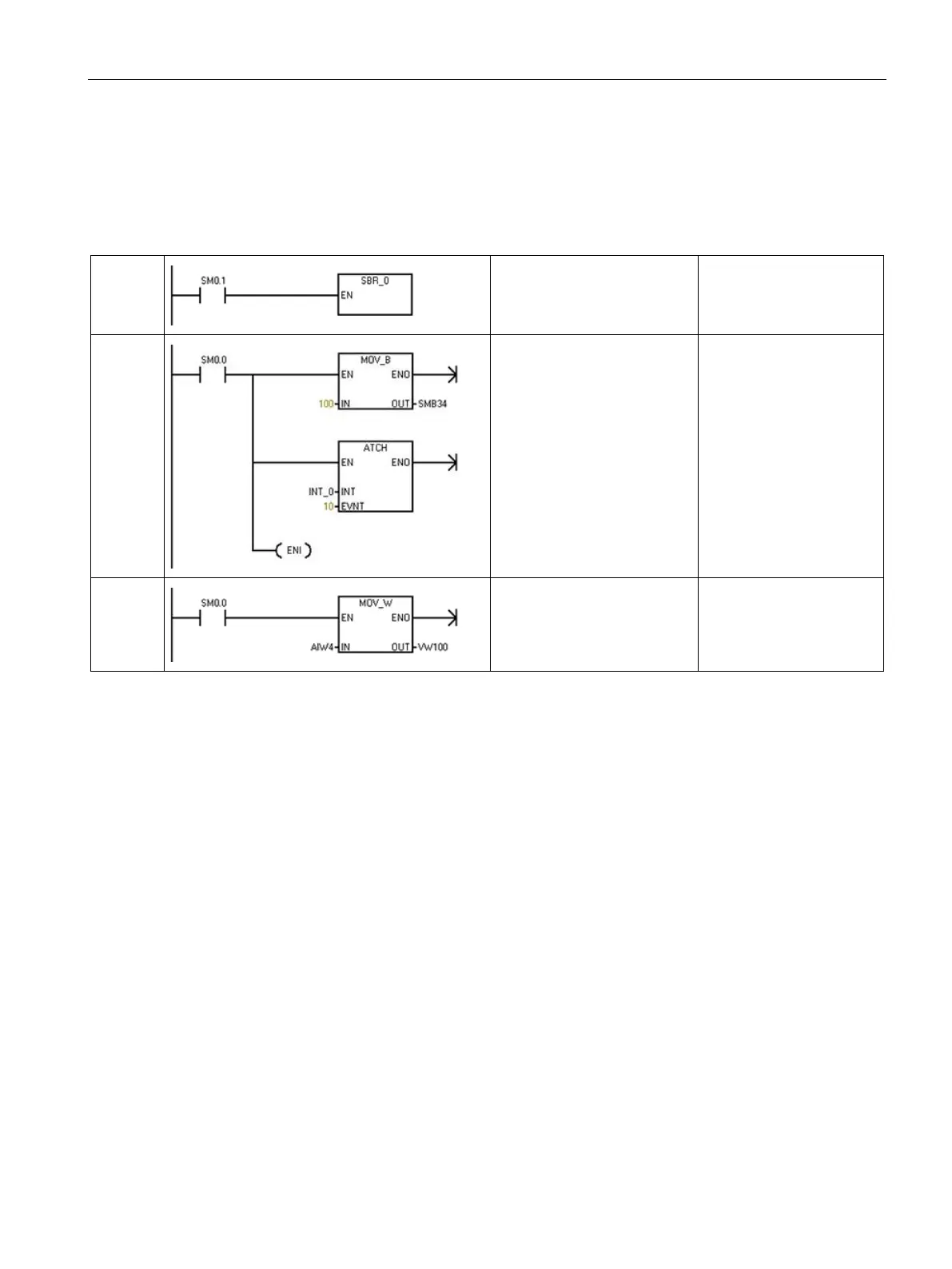
The following example shows a program that includes a subroutine and an interrupt routine.
This sample program uses a timed interrupt for reading the value of an analog input every
100 ms.
Table 5- 1 Sample program with a subroutine and an interrupt routine
Main
Network 1
LD SM0.1
CALL SBR_0
On first scan, call subrou-
tine 0.
SBR 0
Network 1
LD SM0.0
MOVB 100, SMB34
ATCH INT_0, 10
ENI
Set the interval to 100 ms
for the timed interrupt.
Enable interrupt 0.
INT 0
Network 1
LD SM0.0
MOVW AIW4,VW100
Sample the value of analog
input AI4.

Table of Contents

Other manuals for Siemens Simatic S7 Series

Questions and Answers:

Question and Answer IconNeed help?

Do you have a question about the Siemens Simatic S7 Series and is the answer not in the manual?

Siemens Simatic S7 Series Specifications

General IconGeneral
CPUVaries by model (e.g., S7-300, S7-400, S7-1200, S7-1500)
Communication InterfacesPROFIBUS, PROFINET, Ethernet, MPI
ProgrammingTIA Portal, STEP 7
Programming LanguagesLAD, FBD, STL, SCL, GRAPH
I/O ModulesDigital, Analog, Specialty modules available
Operating Temperature0°C to 60°C (standard models)
MountingDIN rail mounting
Operating Voltage24V DC or 120/230V AC (varies by model)
Protection ClassIP20 (standard models)
MemoryVaries depending on the S7 model. Includes work memory (RAM) for program execution, load memory (EEPROM or Flash) for program storage, and system memory for operating system functions. Memory sizes range from kilobytes to megabytes.

Related product manuals