CONVEYOR ENHANCEMENTS
Exit Conveyor Extension Installation
6-84 Aquastorm™ Series Options Guide Rev. 1
6
Procedure Refer to the following steps to connect the electric wires to the jumper strip.
1. Shut down Aquastorm™ system operation.
2. Ensure system power is Off.
3. Perform Lock Out/Tag Out steps. See Lock-Out Tag-Out on page 10.
4. Open the storage cabinet door on the front of the bolt on sound enclosure.
5. Use a phillips screwdriver to remove the four (4) screws holding the electrical
wire cover in place.
6. Review the electrical schematics and ensure all system wires are properly
installed in the jumper connection strip.
7. Replace the electrical wire cover removed in Step 5.
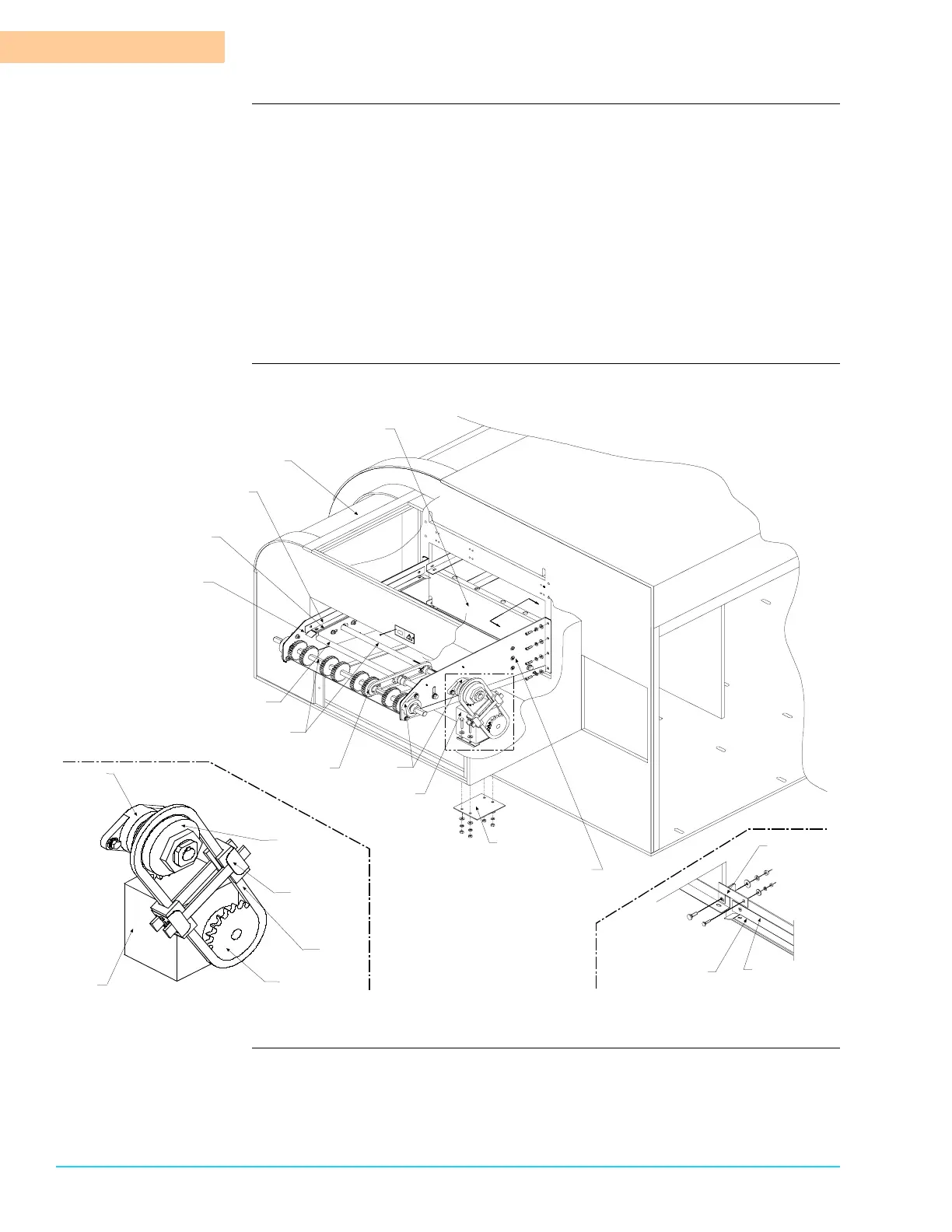
Diagram Figure 6–5 shows the exit conveyor extension installation drawing:
Figure 6–5
Machine Exit End
Left Exit
Conveyor Bracket
Right Exit
Conveyor Bracket
Motor
Bearing
Blocks
Exit Conveyor
Drive Shaft
Sprocket
Assembly
Exit Conveyor
Rail
Exit Conveyor
Wear Strip
Exit Conveyor
Idler Shaft
Rear of
Machine
Sound Enclosure
Unload End
Sound Plate
Motor
Support
Motor
Bearing
Block
Sprocket
Chain
Tensioner
Assembly
Motor
Drive
Chain
Detail A
Detail A
Torque
Limiter
Sprocket
B
B
View B – B
Exit Conveyor
Rail
Exit Conveyor
Wear Strip
Grounding
Bracket