. . . . .
CONVEYOR ENHANCEMENTS
Conveyor Wire Belt Set Up
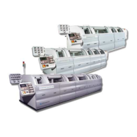
2-9317-600-00-0 Aquastorm™ Series Options Guide 6-89
Procedure Refer to the following steps and Figure on page 88 for conveyor wire belt
installation.
1. Locate and remove the roll of conveyor wire belt from the contents of the
shipment.
2. Bring the roll of wire belt to the entrance end of the Aquastorm™ system.
3. Arrange the wire belt so the Closed End of the Hook Loops face toward the
EXIT end of the Aquastorm system and the smooth side of the wire belt faces
up. Refer to Figure 6–6 on page 87.
4. Manually feed the wire belt from the entrance end of the cabinet through the
TOP PORTION of the conveyor to the exit end.
5. Feed the remaining portion of the wire belt through the bottom portion of the
conveyor until the end of the wire belt reaches the entrance end of the sys-
tem.
6. Assist by pulling the wire belt from the exit end of the conveyor and by reach-
ing inside the window port of each stage and pulling the wire belt through.
7. Using a 13 mm socket head wrench loosen the bolts of the four (4) conveyor
drive shafts on the inlet conveyor to provide enough slack to connect the
beginning and ending sections of the wire belt together.
8. Locate and open the cardboard container labeled Documentation Package
Enclosed and remove the wire belt master links.
9. Install the master links to connect the beginning and ending sections of the
wire belt. For details on master link installation, refer to Wire Belt Splicing
Steps on page 125.
10.Adjust each of the four (4) conveyor drive shafts to ensure consistent tension
is maintained across the wire belt. As each conveyor drive shaft is reposi-
tioned to ensure proper tension, use a 13 mm socket head wrench to tighten
the bolts.
11.Remove Lock Out/Tag Out tags. See Lock-Out Tag-Out on page 10.
12.Replace any front or rear system panels removed during preventive mainte-
nance.
13. Turn system power On.
14.Resume system operation. For detailed information refer to the Aquastorm
200™ or Aquastorm 100™ Programming and Operation Guide.
 Loading...