DRYER MODIFICATIONS
Functional Description
15-276 Aquastorm™ Series Options Guide Rev. 1
15
Control Box A control box mounts at the rear of the machine above the dryer section to house
the solenoid valve, air pressure regulator valve, and air activation timers. Shop air
connects to the solenoid valve then passes through the air pressure valve to the
manifold where the CAT flexible tubing nozzles connect. The solenoid is
connected to the compressed air On and Off timers which start and stop the blast
of compressed air for drying.
The front of the mounting box contains an On/Off push button to turn the CAT
system On or Off as required for processing. Use the air gauge in the mounting
box to verify compressed air flow and pressure.
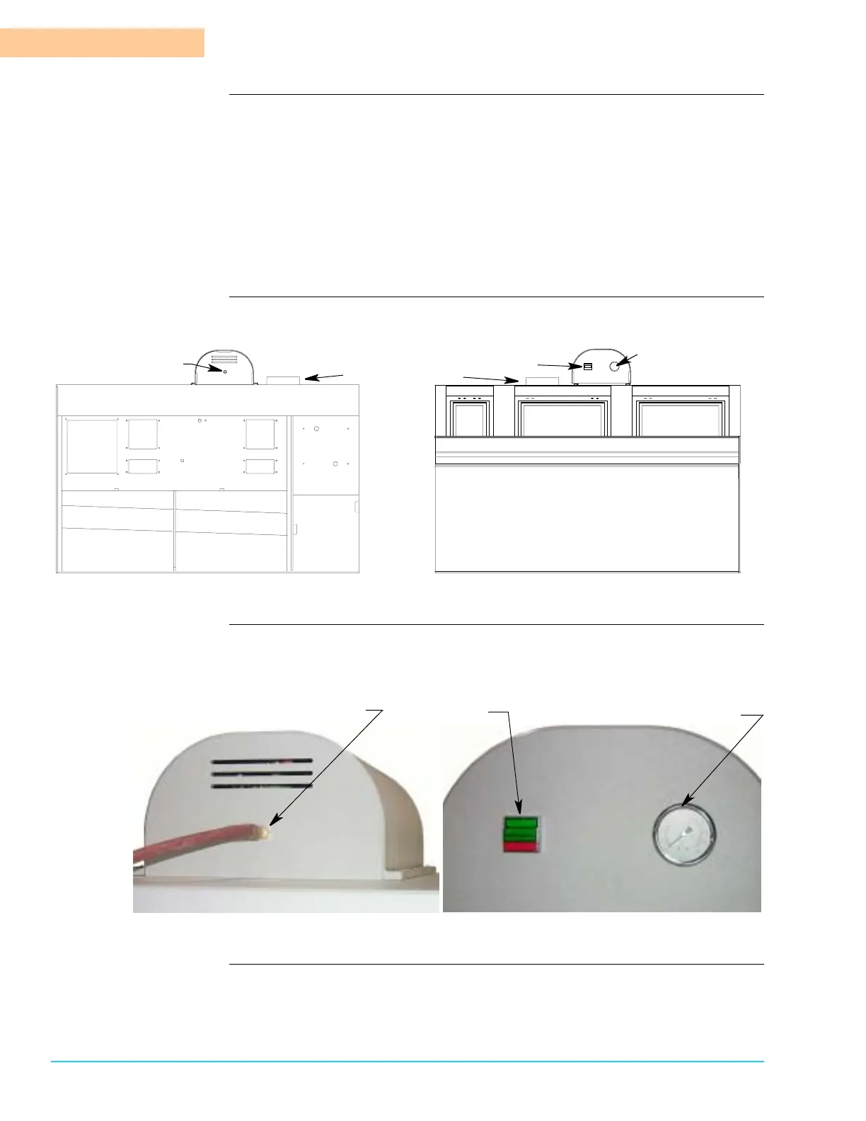
Drawing Figure 15–2 shows the location of the CAT control panel on the system.
Figure 15–2
Photograph Figure 15–3 shows rear and front views of the CAT control panel mounted on the
top bulkhead above the dryer modules.
Figure 15–3
Machine
Exit End
Final
Rinse
Rear
Dryer Blower Section Rear
Final
Rinse
Module
Dryer Modules Front
Machine
Exit End
CAT Control
Panel Rear
Dryer Exhaust Port
CAT On/Off
Button
Front
CAT Compressed
Air Gauge
Compressed
Air to Facility
Connector
Attach Facility
Compressed Air
On/Off
Button
Compressed
Air Gauge