. . . . .
DRYER MODIFICATIONS
Functional Description
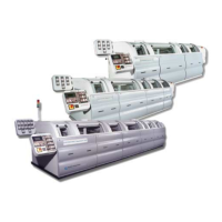
2-9317-600-00-0 Aquastorm™ Series Options Guide 15-277
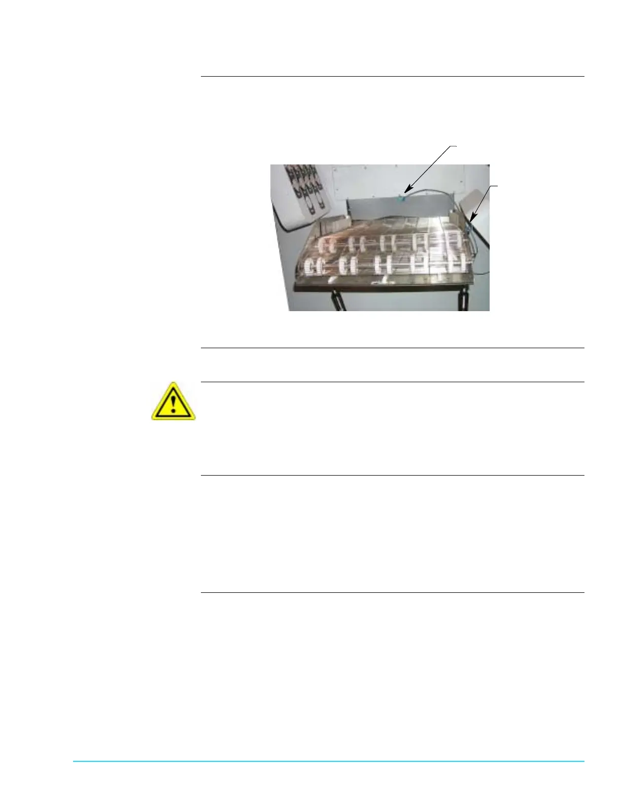
Photographs Figure 15–4 shows an angle adjust entrance end conveyor and identifies the
standard photocell mounting location and the CAT photocell mounting location.
Figure 15–4
Safety To avoid equipment damage observe the following:
CAUTION
Only one (1) photocell can be mounted and configured for operation at the
entrance end of an Aquastorm™ machine. If a photocell is installed, it is moved to
the CAT photocell mounting location. If no photocell is installed a new one is
mounted in the CAT photocell mounting location.
Photocell Processing The process engineer configures the software and sets the compressed air On
and Off timers appropriately. The photocell mounted on the entrance end
bulkhead identifies product as it enters the system. When product arrives at the
CAT nozzle location a blast of compressed air turns On and blows for a
predetermined amount of time. As soon as the product passes the CAT nozzle
location, the compressed air blast turns Off until the next item reaches the CAT
nozzle location. See Timer Configuration on page 279.
Standard Photocell
CAT Photocell
Mounting Location
Mounting Location