SAFETY INFORMATION
Attach Machine Lock-Out Tag-Out Device
-14 Aquastorm™ Series Options Guide Rev. 1
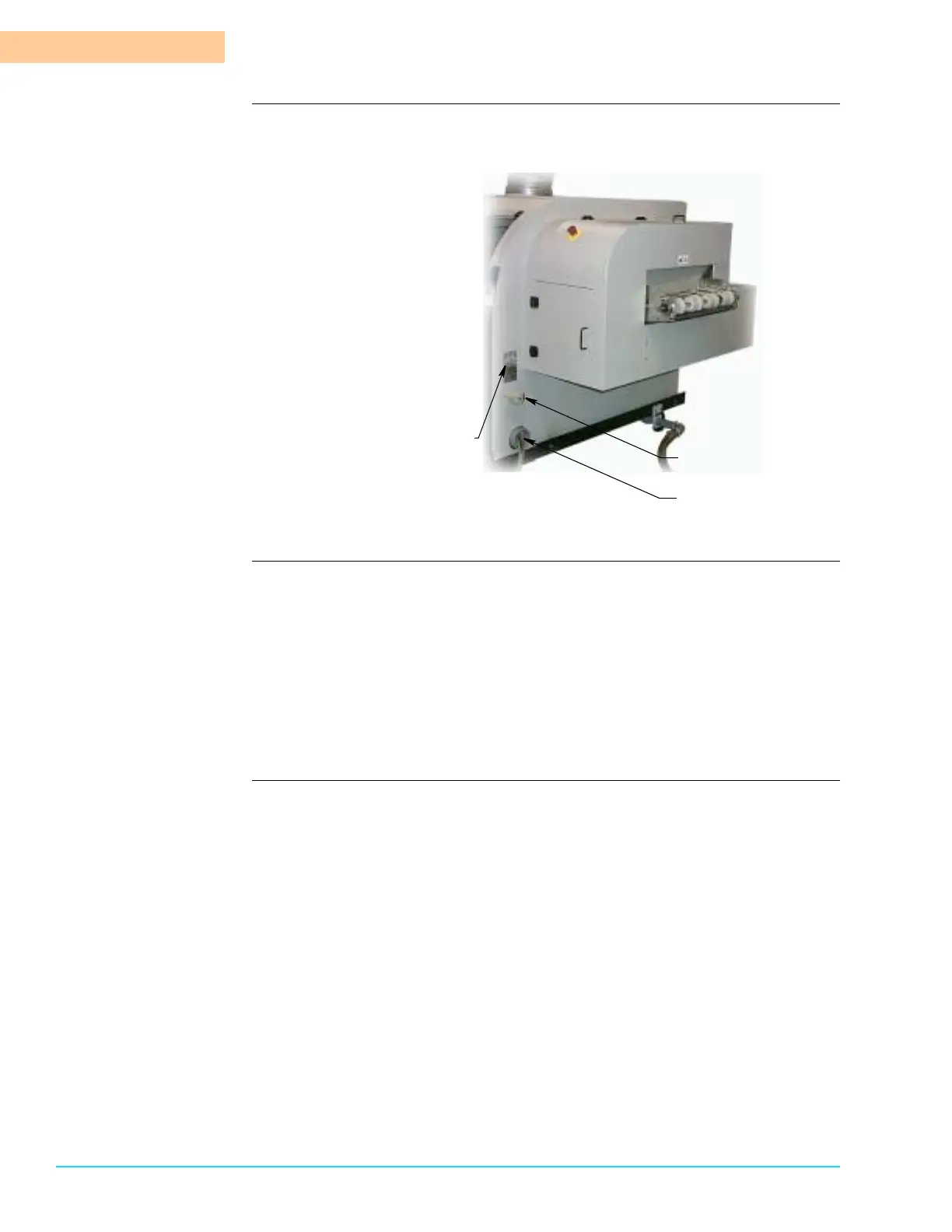
Figure 1–6 shows the exit end of the Aquastorm™ system and identifies the
power switch, incoming power wires, UL and Serial tag locations.
Figure 1–6
Procedure 1. Locate the main power disconnect switch at the exit end of the system.
2. Turn the main disconnect switch to the OFF position.
3. Pull the tab and insert the lock-out device.
4. Secure the lock-out device in place.
5. On systems with an optional EPS (Emergency Power Supply) battery backup
installed, toggle the battery control to the Off position.
6. The system is ready for maintenance, installation, upgrade, or repair proce-
dures.
Main Power Disconnect
Exit End of Machine
Incoming Power Wires
UL and Serial Tags