. . . . .
BLOWER ENHANCEMENTS
Repair
2-9317-600-00-0 Aquastorm™ Series Options Guide 16-311
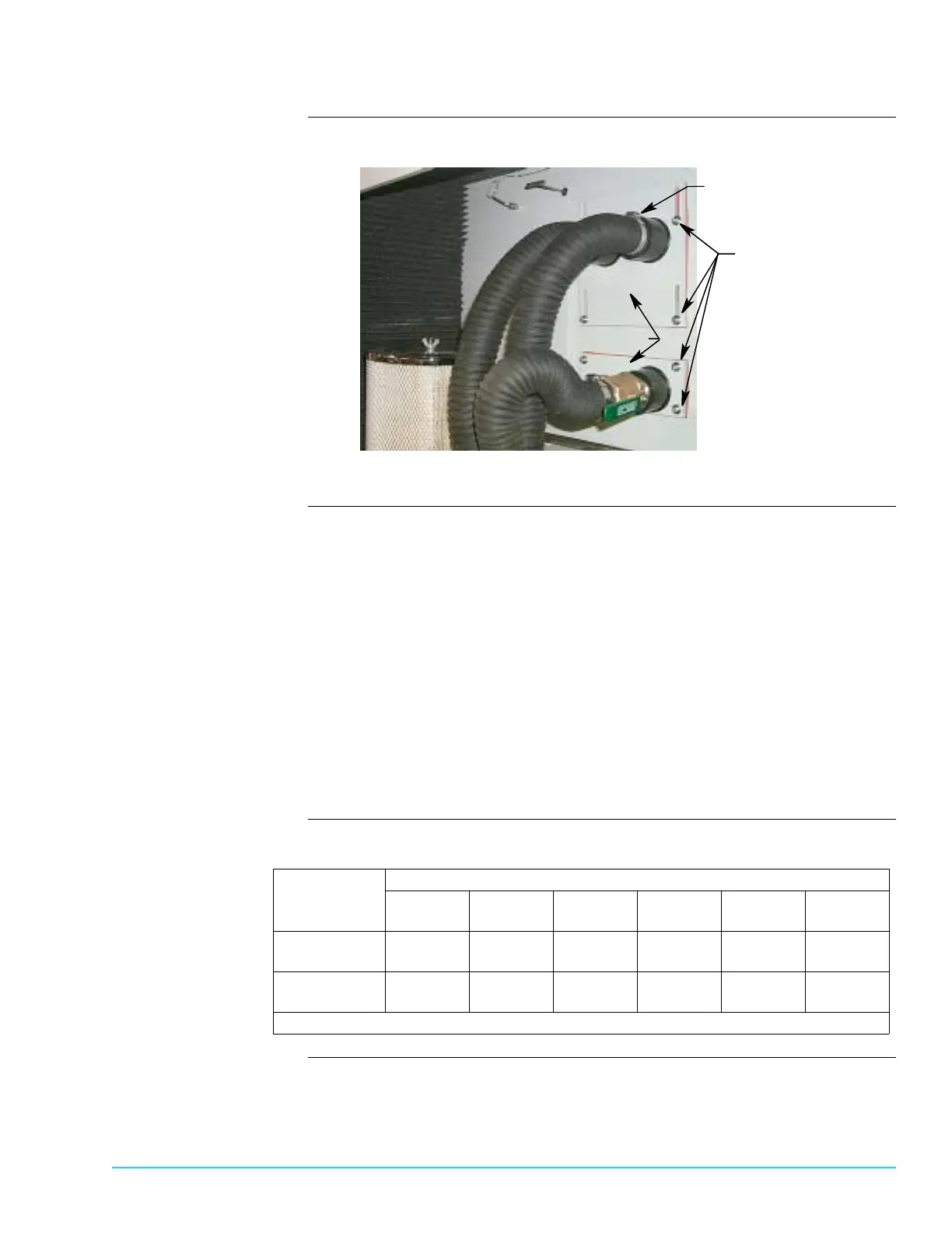
Photograph Figure 16–5 identifies the blower tube mounting
Figure 16–5
Procedure 1. At the rear, blower section, use a flat head screwdriver to loosen the screws
holding the blower hoses to the slide plates and remove the hoses.
2. Use a 5 mm Allen wrench to remove the slide plate mounting screws.
3. Carefully remove the slide plate and attached airknives.
4. Unscrew the airknife from the slide plate.
5. Blow clean shop air into the end of the airknife to remove any debris.
6. Use a feeler gauge to check the airknife gap. Refer to the following table.
7. If necessary, use a 3 mm Allen wrench to adjust the airknife gap.
8. Screw the airknife back into place on the slide plate.
9. Reinstall the airknives in the reverse order of removal.
10.Resume system operation. For detailed information refer to the Aquastorm
200™ or Aquastorm 100™ Programming and Operation Guide.
Table This table lists recommended gap settings for optimum airknife operation:
Slide Plates
Eight (8) Torque Adjust
Mounting Screws
Flat Head Screw
and Hose Clamp
Electrosonic™
Airknife Size
Blower Motor Horsepower Rating
7.5 HP
60 Hz
7.5 HP
50 Hz
10 HP
60 Hz
10 HP
50 Hz
15 HP
60 Hz
15 HP
50 Hz
508 mm
(20 in.)
1.3 mm
(0.050 in.)
1.3 mm
(0.050 in.)
1.5 mm
(0.060 in.)
1.5 mm
(0.060 in.)
2.1 mm
(0.063 in.)
2.1 mm
(0.063 in.)
609.6 mm
(24 in.)
1.1 mm
(0.042 in.)
1.1 mm
(0.042 in.)
1.3 mm
(0.050 in.)
1.3 mm
(0.050 in.)
1.7 mm
(0.065 in.)
1.7 mm
(0.065 in.)
Tolerances are ± 0.3 mm (± 0.002 in.)
 Loading...