5. Click the Manual Adjustment Tab in the Adjust the Motor Current Detection Signal
Offsets Dialog Box.
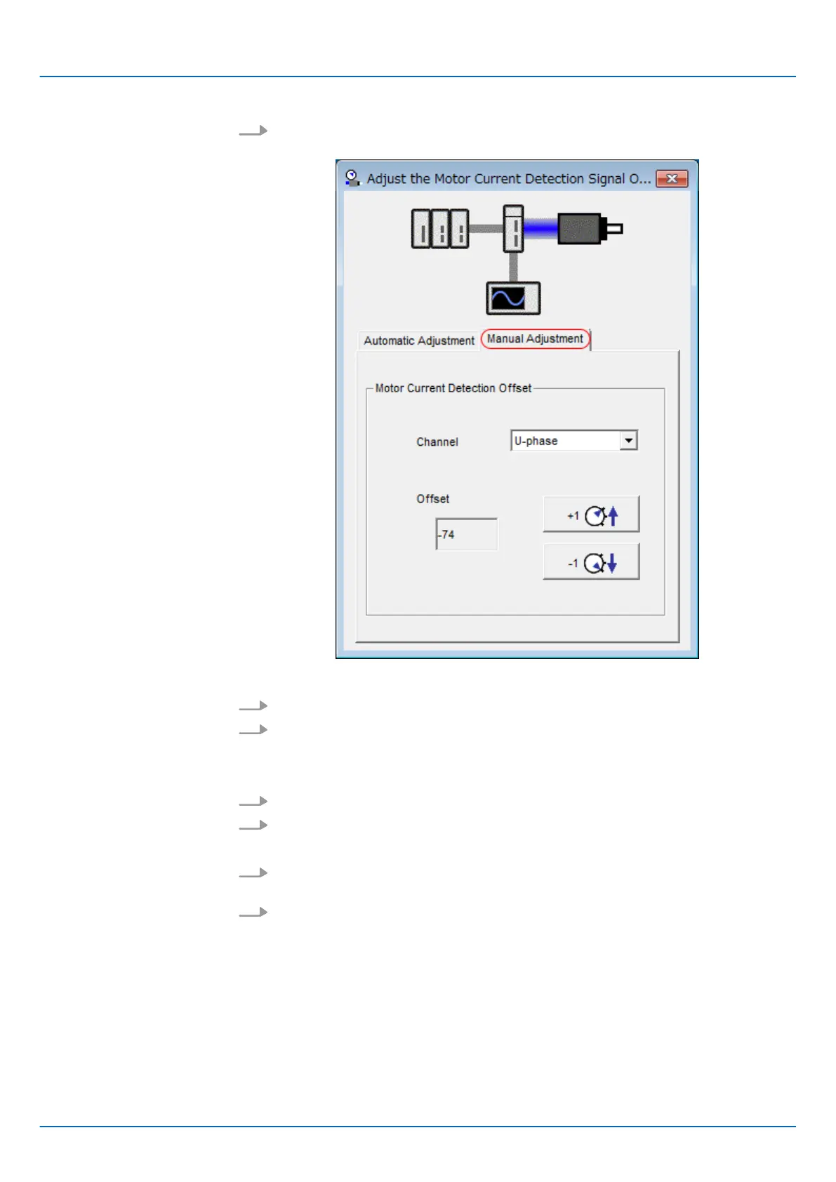
Fig. 196: Adjust the Motor Current Detection Signal Offsets - Manual Adjustment
6. Set the Channel Box in the Motor Current Detection Offset Area to U-phase.
7. Use the +1 and -1 Buttons to adjust the offset for phase U.
Change the offset by about 10 in the direction that reduces the torque ripple.
Adjustment range: -512 to +511
8. Set the Channel Box in the Motor Current Detection Offset Area to V-phase.
9. Use the +1 and -1 Buttons to adjust the offset for phase V.
Change the offset by about 10 in the direction that reduces the torque ripple.
10. Repeat steps 6 to 9 until the torque ripple cannot be decreased any further regard-
less of whether you increase or decrease the offsets.
11. Reduce the amount by which you change the offsets each time and repeat steps 6
to 9.
This concludes the procedure to manually adjust the motor current detection signal offset.
Sigma-7 Series SERVOPACKs
Application Functions
Adjusting the Motor Current Detection Signal Offset > Manual Adjustment
| | PROFINET Communications - SIEP YEUOC7P 02A Revision 0 | en | 257

 Loading...


