3 - 36
Chapter 3 Removal and Replacement Procedures (RRPs)
Version 1 2006.11.28
Removal 21 TONER CARTRIDGE SENSOR ASSEMBLY (C), (M), (Y) (PL5.1.4)
Described below is the removal procedure common among TONER CARTRIDGE SEN-
SOR ASSYs (C), (M), and (Y).
Steps 1 through 7 are for reference. Before removing this component, check that Steps 1 through 7
have been performed.
1) Open FRONT COVER (PL13.2.1).
2) Remove the FUSER.(Removal 8)
3) Remove the REAR COVER. (Removal 49)
4) Remove the COVER BOTTOM. (Removal 50)
5) Remove the COVER POLE IN R.(Removal 51)
6) Remove the COVER POLE R.(Removal 52)
7) Remove the RIGHT COVER. (Removal 54)
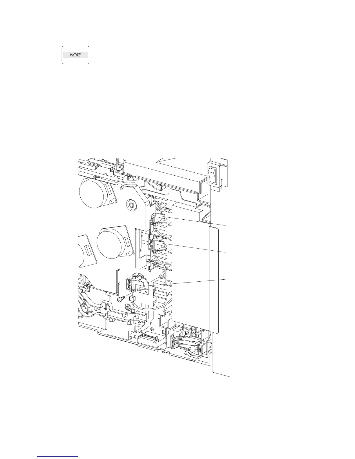
8) Remove the one screw (silver, tap, 10mm) that fixes the TONER CARTRIDGE ASSEMBLY
(PL5.1.4) to the printer.
9) Remove the TONER CARTRIDGE ASSEMBLY from the printer.
10) Disengage the connector of the TONER CARTRIDGE ASSEMBLY.
Gnb03031KA
TONER CARTRIDGE
SENSOR ASSEMBLY (C)
TONER CARTRIDGE
SENSOR ASSEMBLY (M)
TONER CARTRIDGE
SENSOR ASSEMBLY (Y)
8)
9)
10)