3 - 96
Chapter 3 Removal and Replacement Procedures (RRPs)
Version 1 2006.11.28
Removal 66 HUMIDITY SENSOR (PL13.5.11)
Steps 1 through 9 are for reference. Before removing this component, check that Steps 1 through 9
have been performed.
1) Open the FRONT COVER (PL13.2.1).
2) Remove the FUSER. (Removal 8)
3) Remove the REAR COVER. (Removal 49)
4) Remove the COVER BOTTOM. (Removal 50)
5) Remove the COVER POLE IN L. (Removal 57)
6) Remove the COVER POLE L. (Removal 58)
7) Remove the LEFT COVER. (Removal 59)
8) Remove the BOX ASSY PRT AIO. (Removal 60)
9) Remove the BOX ASSY FAX AIO. (Removal 62)
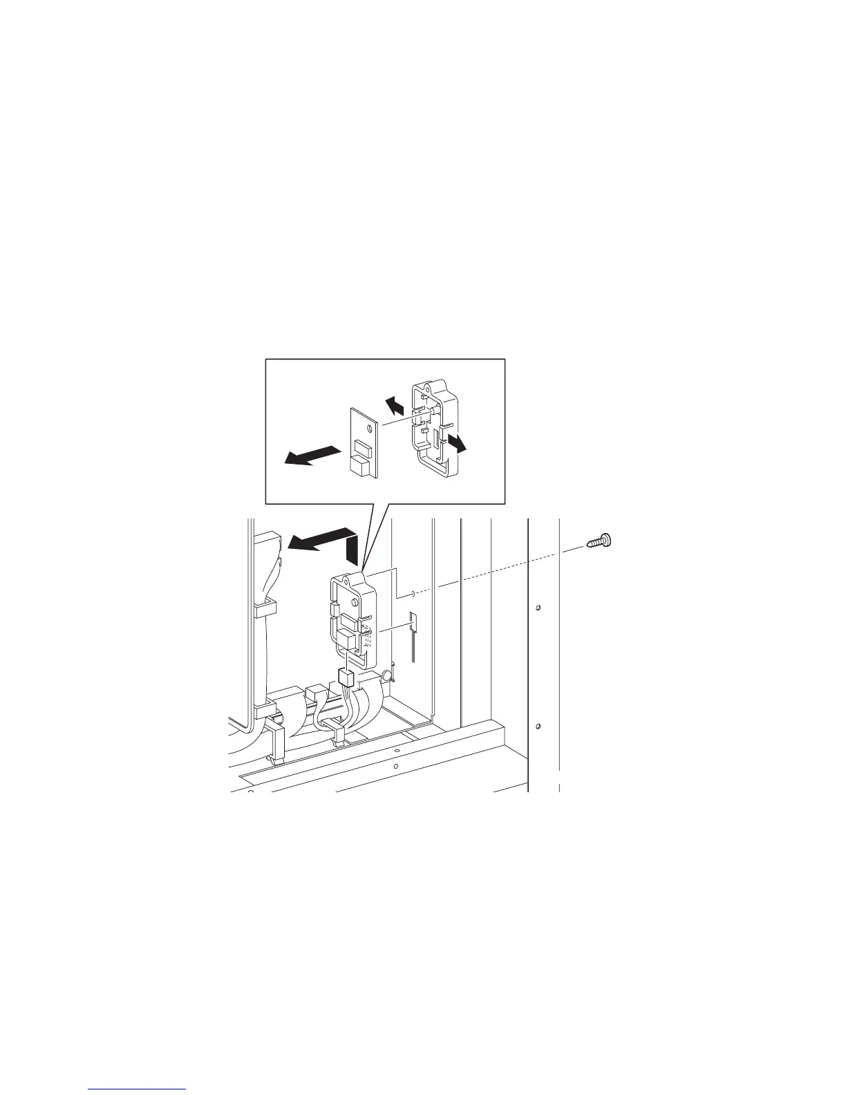
10) Remove the one screw (silver, tap, 10mm) that fixes the BRACKET SENSOR HUM
(PL13.5.12) to the printer.
11) Remove the BRACKET SENSOR HUM together with the HUMIDITY SENSOR (PL13.5.11)
by sliding the BRACKET SENSOR HUM upward until its hooks are released from the holes
on the printer.
12) Disengage the connector (P/J261) of the HUMIDITY SENSOR.
13) Remove the HUMIDITY SENSOR from the BRACKET SENSOR HUM by releasing the hooks
on the BRACKET SENSOR HUM.
Go to the next removal step:
Removal 67 MACHINE CONTROL UNIT (PL13.5.13)
Gnb03175KA
10)
11)
12)
13)-1
13)-1
13)-2