3 - 144
Chapter 3 Removal and Replacement Procedures (RRPs)
Version 1 2006.11.28
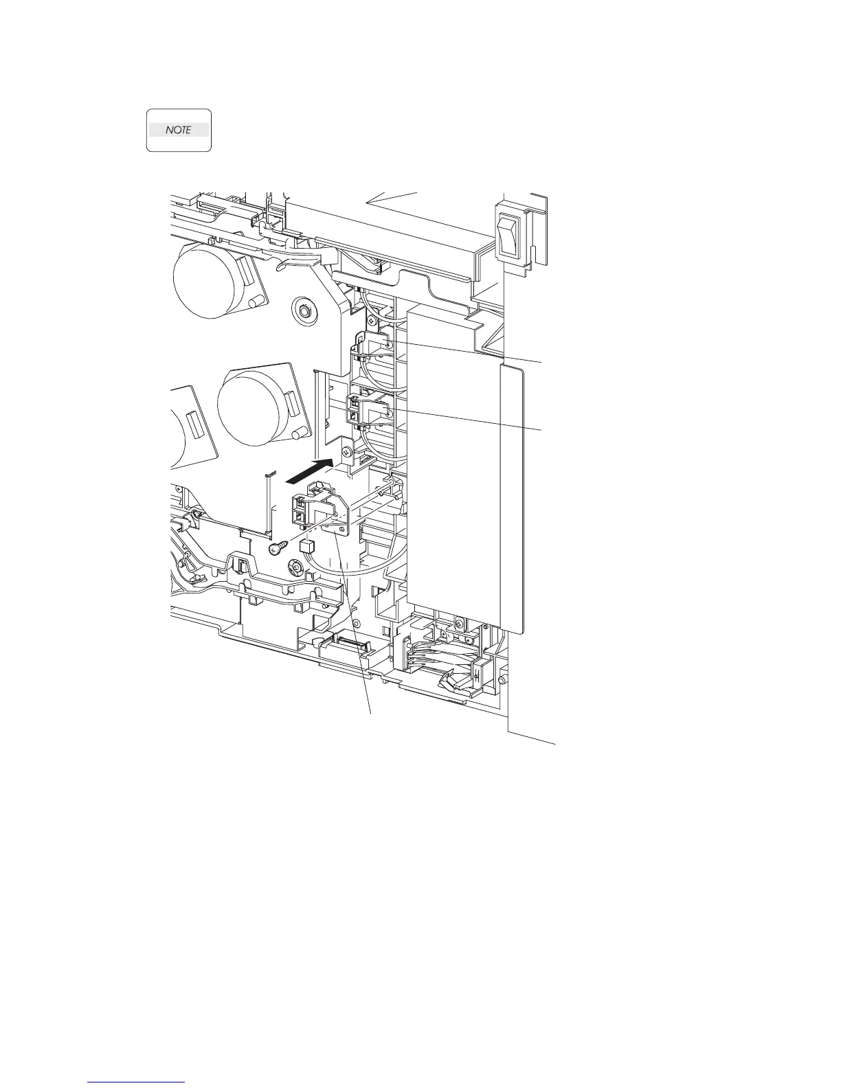
Replacement 25 TONER CARTRIDGE SENSOR ASSEMBLY (C), (M), (Y) (PL5.1.4)
Described below is the replacement procedure common among TONER CARTRIDGE
SENSOR ASSYs (C), (M), and (Y).
1) Engage the connector of the TONER CARTRIDGE SENSOR ASSEMBLY.
2) Mate the two holes on the TONER CARTRIDGE SENSOR ASSEMBLY with the bosses on the
printer.
3) Secure the TONER CARTRIDGE SENSOR ASSEMBLY to the printer using the one screw
(silver, tap, 10mm).
Go to the next replacement step:
Replacement 68 RIGHT COVER (PL13.1.9)
Gnb03091KA
TONER CARTRIDGE
SENSOR ASSEMBLY (C)
TONER CARTRIDGE
SENSOR ASSEMBLY (M)
TONER CARTRIDGE
SENSOR ASSEMBLY (Y)
3)
2)
1)