3 - 41
Chapter 3 Removal and Replacement Procedures (RRPs)
Version 1 2006.11.28
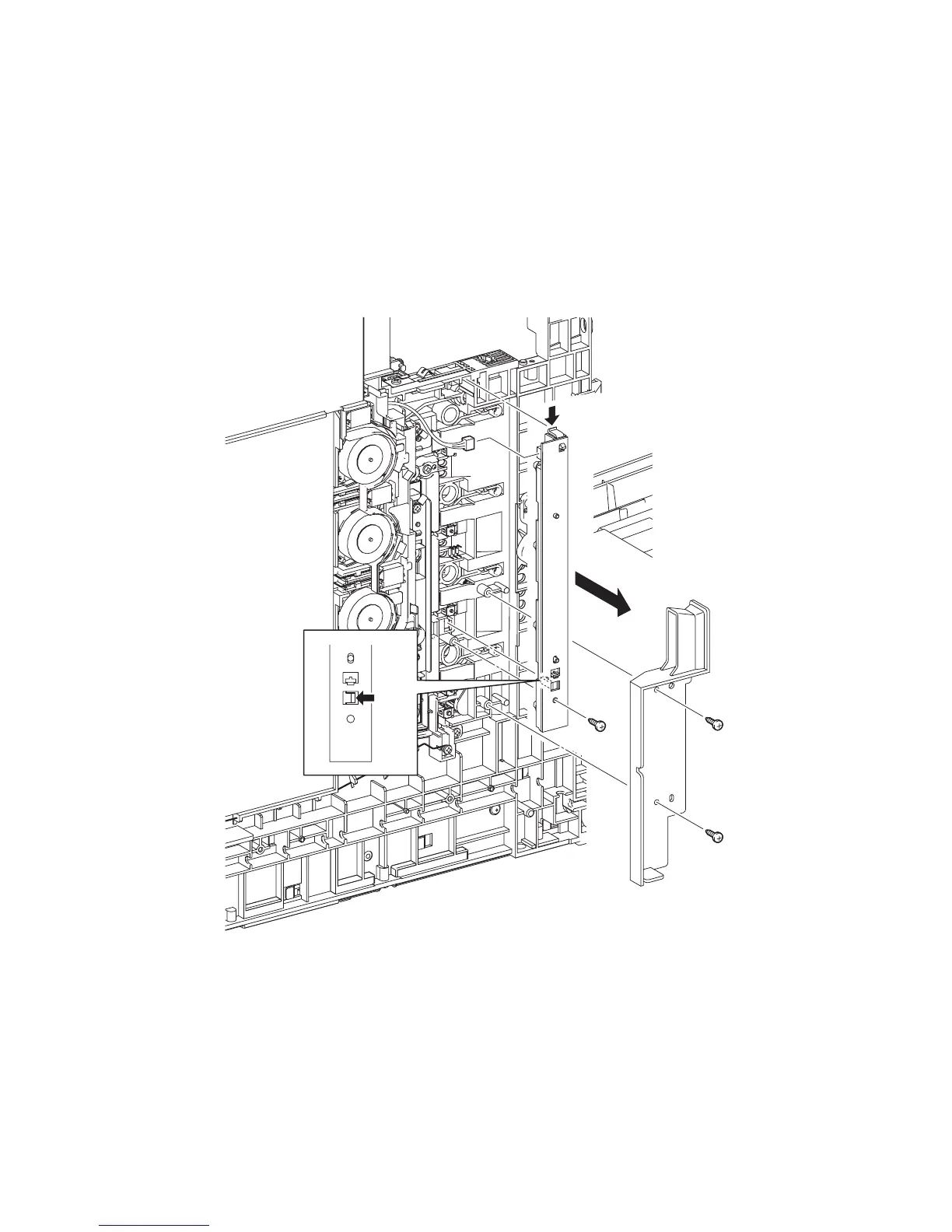
Removal 25 LED ASSEMBLY (PL5.1.15)
Steps 1 through 7 are for reference. Before removing this component, check that Steps 1 through 7
have been performed.
1) Open FRONT COVER (PL13.2.1).
2) Remove the FUSER. (Removal 8)
3) Remove the REAR COVER. (Removal 49)
4) Remove the COVER BOTTOM. (Removal 50)
5) Remove the COVER POLE IN L. (Removal 57)
6) Remove the COVER POLE L. (Removal 58)
7) Remove the LEFT COVER. (Removal 59)
8) Remove the two screws (silver, tap, 8mm) that fix the DUCT SIDE L (PL7.1.23) to the printer.
9) Remove the DUCT SIDE L from the printer.
10) Remove the one screw (silver, tap, 10mm) that fixes the LED ASSEMBLY (PL5.1.15) to the
printer.
11) Remove the LED ASSEMBLY from the printer by releasing its two hooks.
12) Disengage the connector (P/J141) of the LED ASSEMBLY.
Gnb03037KA
10)
9)
8)
8)
11)-1
11)-1
11)-2
12)