3 - 89
Chapter 3 Removal and Replacement Procedures (RRPs)
Version 2 2007.03.20
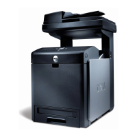
Removal 60 BOX ASSY PRT AIO (PL13.4.13)
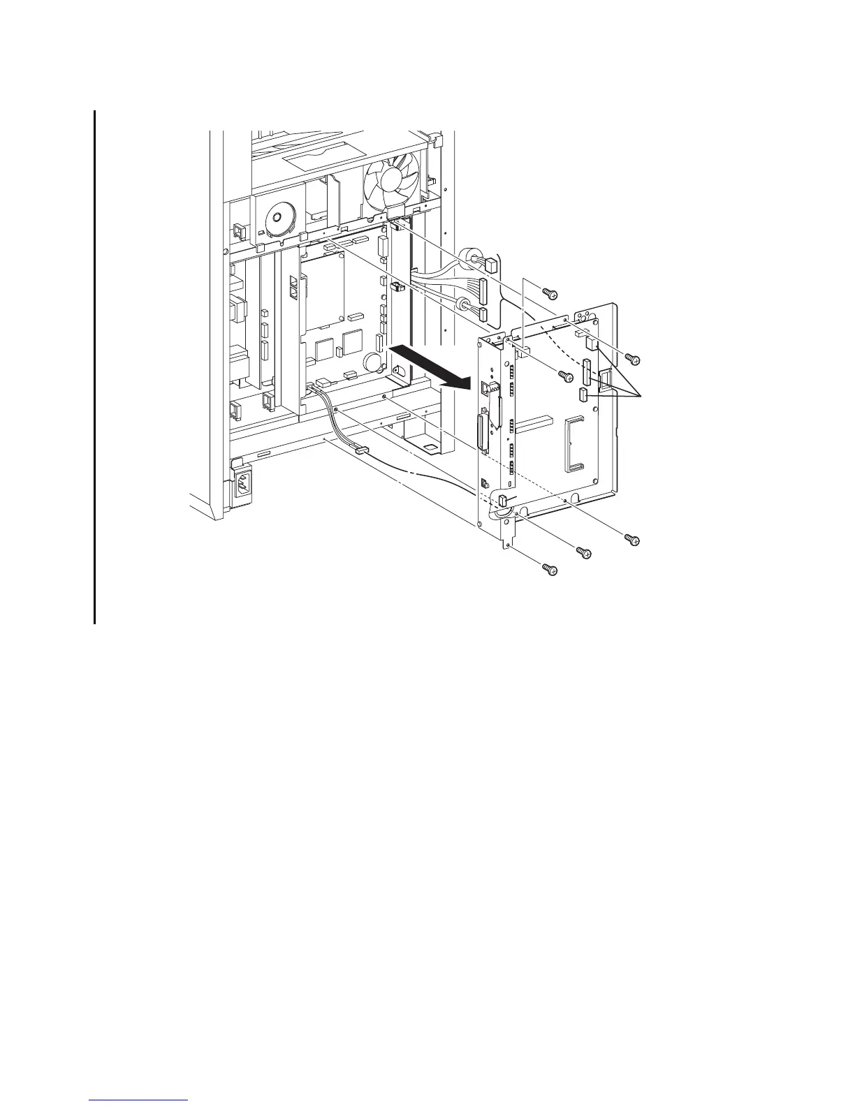
8) Disengage all the connectors of the ELECTRONIC SUB-SYSTEM CONTROL BOARD
(PL13.4.20).
9) Remove the six screws (silver,6mm) that fix the BOX ASSY PRT AIO (PL13.4.13) to the
printer.
10) Pull out the BOX ASSY PRT AIO slightly forward, and then release the three harnesses on
the right from the CLAMP SADDLE LES-1017 (PL13.4.19).
11) Disengage the connector of the HARNESS ASSY AIO-ESS (PL13.6.14) from the
ELECTRONIC SUB-SYSTEM CONTROL BOARD. Remove from the printer the BOX ASSY
PRT AIO together with the ELECTRONIC SUB-SYSTEM CONTROL BOARD while pulling
out the HARNESS ASSY AIO-ESS through the hole on the BOX ASSY PRT AIO.
Go to the next removal steps:
Removal 61 ELECTRONIC SUB-SYSTEM CONTROL BOARD (PL13.4.20), Removal 62
BOX ASSY FAX AIO (PL13.4.4), Removal 63 PWBA FAX (PL13.4.3), Removal 69
SPEAKER ASSY (PL13.5.6) or Removal 72 ADF SCANNER ASSY (PL13.8.1)
Gnb03168KB
8)
9)
10)
9)
9)
9)
9)
9)
11)-1
11)-2
8)