3 - 148
Chapter 3 Removal and Replacement Procedures (RRPs)
Version 2 2007.03.20
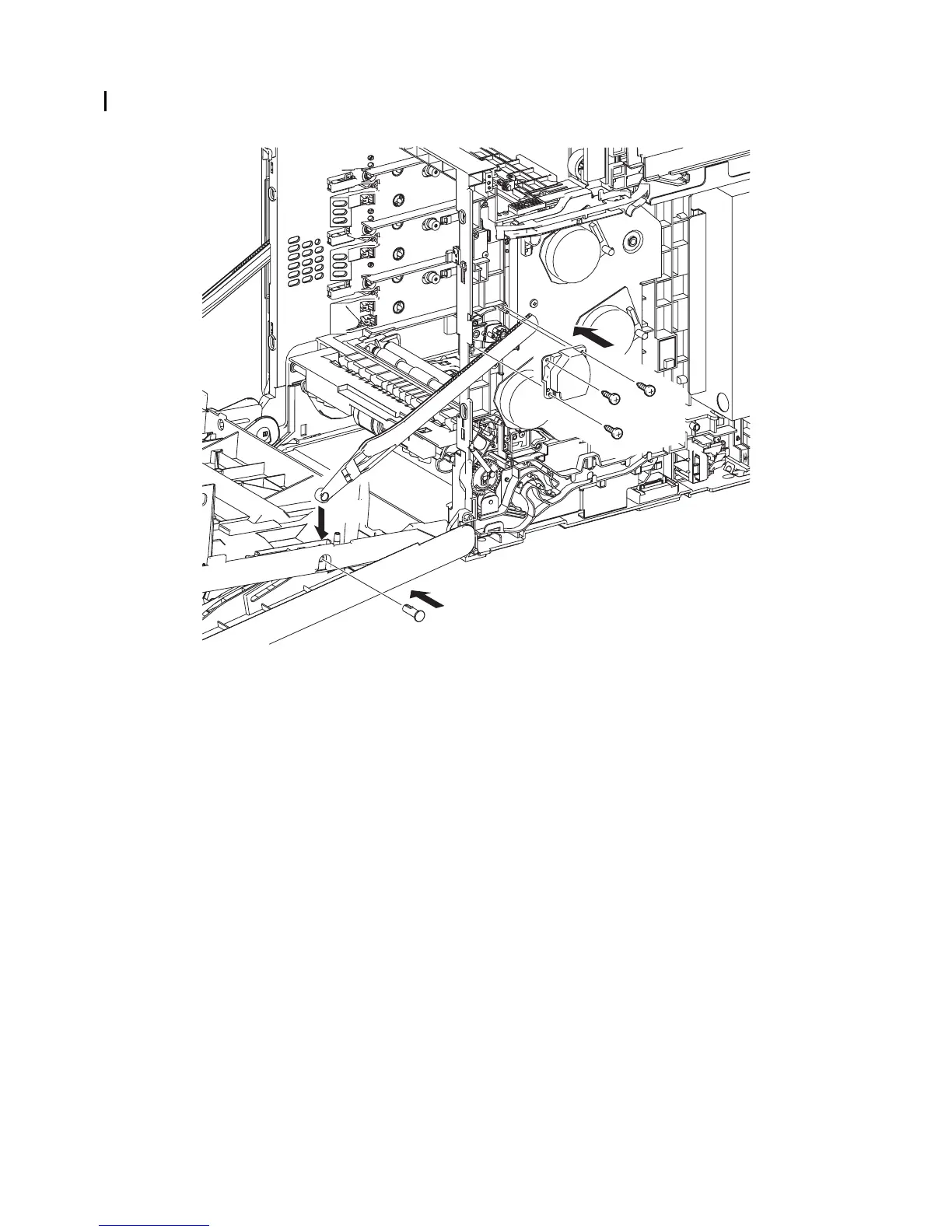
Replacement 28 RIGHT ARM ASSEMBLY (PL13.3.98)
5) Replace the SUPPORT LINK R by mating the two holes on the SUPPORT LINK R with the
bosses on the printer.
6) Secure the SUPPORT LINK R to the printer using the three screws (silver, tap, 8mm).
7) Mate the fitting hole on the LINK R with the right side fitting hole on the FRONT COVER.
Insert the SHAFT PIVOT and secure using the hook.
Go to the next replacement step:
Replacement 68 RIGHT COVER (PL13.1.9)
Gnb03088KA
7)-2
5)
7)-1
6)
6)
6)