GD32VF103 User Manual
155
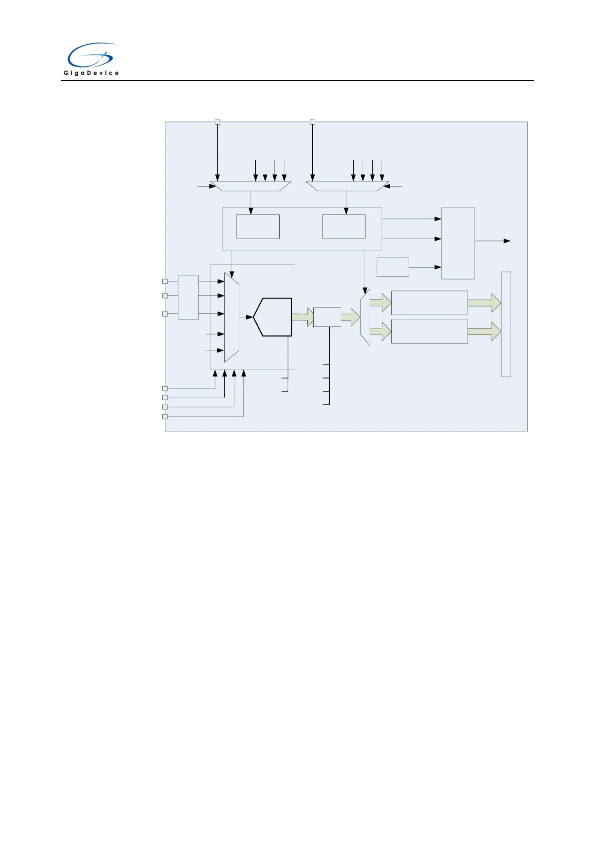
ADC_IN0
ADC_IN1
· · ·
ADC_IN15
GPIO
Channel selector
VSENSE
VREFP
VREFN
VDDA
VSSA
6
~
12
bit
Injected data registers
(16 bits x 4)
Regular data registers
(16 bits)
Regular
channels
Inserted
channels
Channel Management
Trig select
EXTI11
TIMER0_CH0
TIMER0_CH1
TIMER0_CH2
TIMER1_CH1
Trig select
EXTI15
TIMER0_TRGO
TIMER0_CH3
TIMER1_TRGO
TIMER1_CH0
Analog
watchdog
A
P
B
B
U
S
EOC
EOIC
watchdog
event
Interrupt
generator
ADC
Interrupt
SAR ADC
CLB
self calibration
DRES[1:0]
12, 10, 8, 6 bits
OVSS[3:0]
OVSR[2:0]
OVSEN
TOVS
Over
sampler
… …
VREFINT
11.4.1. Calibration (CLB)
The ADC has a foreground calibration feature. During the procedure, the ADC calculates a
calibration factor which is internally applied to the ADC until the next ADC power-off. The
application must not use the ADC during calibration and must wait until it is completed.
Calibration should be performed before starting A/D conversion. The calibration is initiated by
software by setting bit CLB=1. CLB bit stays at 1 during all the calibration sequence. It is then
cleared by hardware as soon as the calibration is completed.
When the ADC operating conditions change (such as supply power voltage V
DDA
, positive
reference voltage V
REF+
, temperature and so on), it is recommended to re-run a calibration
cycle.
The internal analog calibration can be reset by setting the RSTCLB bit in ADC_CTL1 register.
Calibration software procedure:
1. Ensure that ADCON=1.
2. Delay 14 ADCCLK to wait for ADC stability.
3. Set RSTCLB (optional).
4. Set CLB=1.
5. Wait until CLB=0.