GD32VF103 User Manual
228
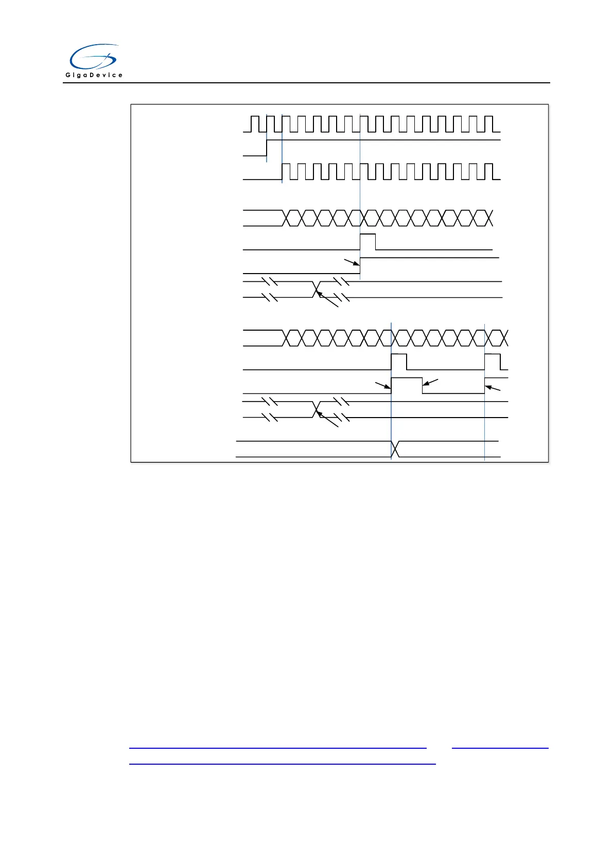
Figure 15-5. Timing chart of up counting mode, change TIMERx_CAR ongoing
TIMER_CK
CEN
CNT_CLK(PSC_CLK)
CNT_REG
5E 5F 60 61 62 63
00 01 02 03 04
05 06 07
Update event (UPE)
Update interrupt flag (UPIF)
Auto-reload register
65
63
change CAR Vaule
CNT_REG
5E 5F 60 61 62 63
64 65 00 01 02
62 63 00
Update event (UPE)
Update interrupt flag (UPIF)
Auto-reload register
65
63
change CAR Vaule
65 63
Auto-reload shadow
register
...
Hardware set
Hardware set
Software clear
Hardware set
ARSE = 0
ARSE = 1
Down counting mode
In this mode, the counter counts down continuously from the counter reload value, which is
defined in the TIMERx_CAR register, in a count-down direction. Once the counter reaches 0,
the counter restarts to count again from the counter reload value. If the repetition counter is
set, the update event will be generated after (TIMERx_CREP+1) times of underflow.
Otherwise, the update event is generated each time when counter underflows. The counting
direction bit DIR in the TIMERx_CTL0 register should be set to 1 for the down-counting mode.
When the update event is set by the UPG bit in the TIMERx_SWEVG register, the counter
value will be initialized to the counter reload value and an update event will be generated.
If the UPDIS bit in TIMERx_CTL0 register is set, the update event is disabled.
When an update event occurs, all the registers (repetition counter register, auto reload
register, prescaler register) are updated.
Figure 15-6. Timing chart of down counting mode, PSC=0/1 and Figure 15-7. Timing
chart of down counting mode, change TIMERx_CAR ongoing show some examples of
the counter behavior in different clock frequencies when TIMERx_CAR = 0x63.