GD32VF103 User Manual
320
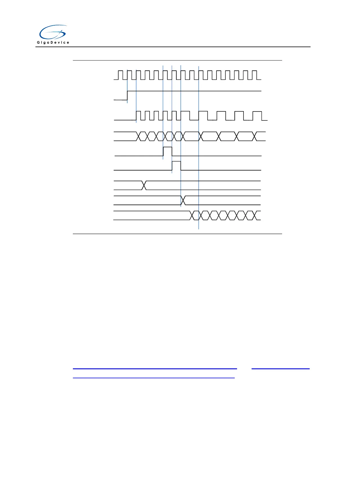
Figure 15-54. Counter timing diagram with prescaler division change from 1 to 2
TIMER_CK
CEN
PSC_CLK
CNT_REG
Reload Pulse
Prescaler CNT
Prescaler BUF
F7 F8 F9 FA FB FC 01 02 03
0
1
0 1
0 1
0 1
0 1
0 1
PSC value
0 04
UPG
0
Up counting mode
In this mode, the counter counts up continuously from 0 to the counter-reload value, which is
defined in the TIMERx_CAR register, in a count-up direction. Once the counter reaches the
counter reload value, the counter restarts to count once again from 0.The update event is
generated at each counter overflow.
When the update event is set by the UPG bit in the TIMERx_SWEVG register, the counter
value will be initialized to 0 and generates an update event.
If set the UPDIS bit in TIMERx_CTL0 register, the update event is disabled.
When an update event occurs, all the registers (repetition counter, auto reload register,
prescaler register) are updated.
Figure 15-55. Timing chart of up counting mode, PSC=0/1 and Figure 15-56. Timing
chart of up counting mode, change TIMERx_CAR ongoing show some examples of the
counter behavior for different clock prescaler factor when TIMERx_CAR=0x63.